
Method and system for link aggregation across multiple switches

a technology of link aggregation and switch, applied in the field of network management, can solve problems such as unsolved problems and existing technologies that do not provide scalable and flexible solutions

Active Publication Date: 2011-12-08
AVAGO TECH INT SALES PTE LTD
View PDF4 Cites 169 Cited by
  • Summary
  • Abstract
  • Description
  • Claims
  • Application Information

AI Technical Summary

Benefits of technology

[0012]In a variation on this embodiment, the switch is a layer-2 switch capable of routing without requiring the network topology to be based on a spanning tree.

Problems solved by technology

While TRILL brings many desirable features to layer-2 networks, some issues remain unsolved when TRILL-capable devices are coupled with non-TRILL devices.
Particularly, when a non-TRILL device is coupled to multiple TRILL devices using link aggregation, existing technologies do not provide a scalable and flexible solution that takes full advantage of the TRILL network.

Method used


Image

  • Method and system for link aggregation across multiple switches
  • Method and system for link aggregation across multiple switches
  • Method and system for link aggregation across multiple switches

Examples


Embodiment Construction

[0025]The following description is presented to enable any person skilled in the art to make and use the invention, and is provided in the context of a particular application and its requirements. Various modifications to the disclosed embodiments will be readily apparent to those skilled in the art, and the general principles defined herein may be applied to other embodiments and applications without departing from the spirit and scope of the present invention. Thus, the present invention is not limited to the embodiments shown, but is to be accorded the widest scope consistent with the claims.

Overview

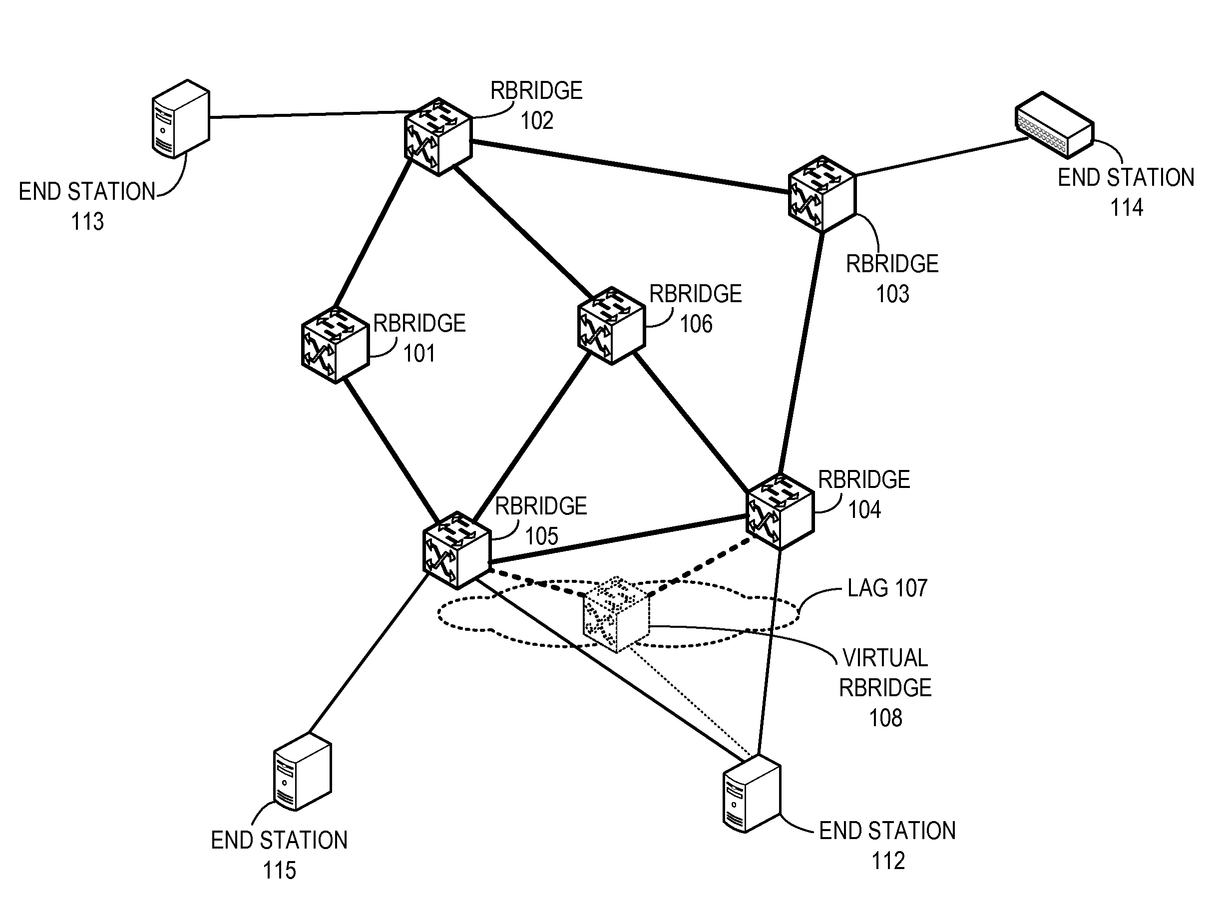
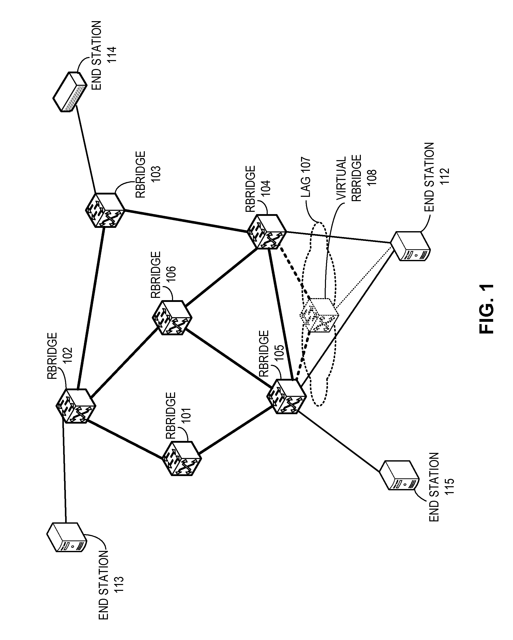
[0026]In embodiments of the present invention, the problem of providing a scalable and flexible way of provisioning multi-switch link aggregation in a TRILL network is solved by forming a logical, virtual RBridge corresponding to a link aggregation group across multiple RBridges and assigning a virtual RBridge identifier based on the link aggregation group (LAG) identifier. For exampl...


PUM


Abstract

One embodiment of the present invention provides a switch. The switch includes a forwarding mechanism and a control mechanism. During operation, the forwarding mechanism forwards frames based on their Ethernet headers. The control mechanism operates the switch in conjunction with a separate physical switch as a single logical switch and assigns a virtual switch identifier to the logical switch, wherein the virtual switch identifier is associated with a link aggregation group.

Description

RELATED APPLICATIONS[0001]This application claims the benefit of U.S. Provisional Application No. 61 / 352,720, Attorney Docket Number BRCD-3024.0.1.US.PSP, entitled “Method and Apparatus For Link Aggregation Across Multiple Switches,” by inventors Joseph Juh-En Cheng, Wing Cheung, John Michael Terry, Suresh Vobbilisetty, Surya P. Varanasi, and Parviz Ghalambor, filed 8 Jun. 2010, the disclosure of which is incorporated by reference herein.[0002]The present disclosure is related to US Patent Application No. 12 / 725,249, (attorney docket number BRCD-112-0439US), entitled “REDUNDANT HOST CONNECTION IN A ROUTED NETWORK,” by inventors Somesh Gupta, Anoop Ghanwani, Phanidhar Koganti, and Shunjia Yu, filed 16 Mar. 2010; and[0003]U.S. patent application Ser. No. 13 / 087,239, (attorney docket number BRCD-3008.1.US.NP), entitled “VIRTUAL CLUSTER SWITCHING,” by inventors Suresh Vobbilisetty and Dilip Chatwani, filed 14 Apr. 2011;[0004]the disclosures of which are incorporated by reference herein....

Claims


Application Information

Patent Timeline
Patent Type & Authority Applications(United States)
IPC IPC(8): H04L12/56H04L45/243
CPCH04L12/4625H04L12/4633H04L45/00Y02B60/33H04L45/66H04L49/70H04L45/245Y02D30/50
Inventor CHENG, JOSEPH JUH-ENCHEUNG, WINGTERRY, JOHN MICHAELVOBBILISETTY, SURESHVARANASI, SURYA P.GHALAMBOR, PARVIZ
Owner AVAGO TECH INT SALES PTE LTD
Learn More