Method of producing a high quality, high resolution image from a sequence of low quality, low resolution images that are undersampled and subject to jitter

a high-resolution image and sequence technology, applied in the field of digital image processing, can solve the problems of inability to identify suspects, difficulty in identifying suspects, and inability to capture images with high-resolution, so as to increase the quality and pixel count of frames, and improve the quality of image data. , the effect of simple and computationally efficien

Inactive Publication Date: 2003-11-18
NYTELL SOFTWARE LLC
View PDF32 Cites 132 Cited by
  • Summary
  • Abstract
  • Description
  • Claims
  • Application Information

AI Technical Summary

Benefits of technology

Accordingly, several objects and advantages of our invention are:
1. To stabilize video and simultaneously allow for electronic zoom or upsampling at a higher pixel count;
2. To increase the quality and pixel count of frames in a video sequence using a simple and computationally efficient algorithm that operates in real-time;
3. To stabilize the frames in a video sequence using a simple and computationally efficient algorithm that operates in real-time;

Problems solved by technology

Image data often does not contain as much fine detail as desired for an intended use.
A news video of a car chase may be smeared and jittery because of the long distance between the airborne camera and the subject, and because of the instability of the helicopter that carries the camera.
An image derived from a security video of a crime scene may be so coarse and so smeared that identification of the suspect is difficult, if not impossible.
An x-ray image at an airport check-in facility may be so coarse that the operator misses the wires in an explosive triggering device.
An image from a video camera at a law enforcement site or toll road entry may be too coarse to recognize the alphanumeric digits on a license plate.
An infrared image from a military reconnaissance video may be too coarse and jittery to identify vehicles on the ground.
A real-world sensor, however, has sensor elements of measurable size and spacing that tend to cause certain imaging limitations.
As such, the image sensor is unable to capture all of the available detail in a single LPC frame, and until now, no practical video processing was available to analyze two or more LPC frames in order to recover such detail and transfer such detail to one or more high pixel count frames (HPC frames).
There have been previous attempts to increase the stability of video sequences, but these have not exploited the jitter in the original scene to create higher resolution.
Commercial video cameras available to consumers have crude electronic stabilization capability, but do not significantly increase the resolution of the video produced.
Video editing systems may electronically "zoom" or "upsample" the frames, and they may stabilize the zoomed frames based on prior frames, but they do not use image data from the prior frames to improve the spatial details in the zoomed frame.
The second method results in an excessively smoothed or blurred image lacking the spatial details and edge definition that was present in the optical image that was impinging on the image sensor during the formation of the LPC frame.
The preceding consumer products try to improve jittery, low pixel count video, but they do not exploit spatial detail that is hidden within a jittery succession of LPC frames.
This trial and error approach obviously has limited, real-time uses.

Method used


Image

  • Method of producing a high quality, high resolution image from a sequence of low quality, low resolution images that are undersampled and subject to jitter
  • Method of producing a high quality, high resolution image from a sequence of low quality, low resolution images that are undersampled and subject to jitter
  • Method of producing a high quality, high resolution image from a sequence of low quality, low resolution images that are undersampled and subject to jitter

Examples


Embodiment Construction

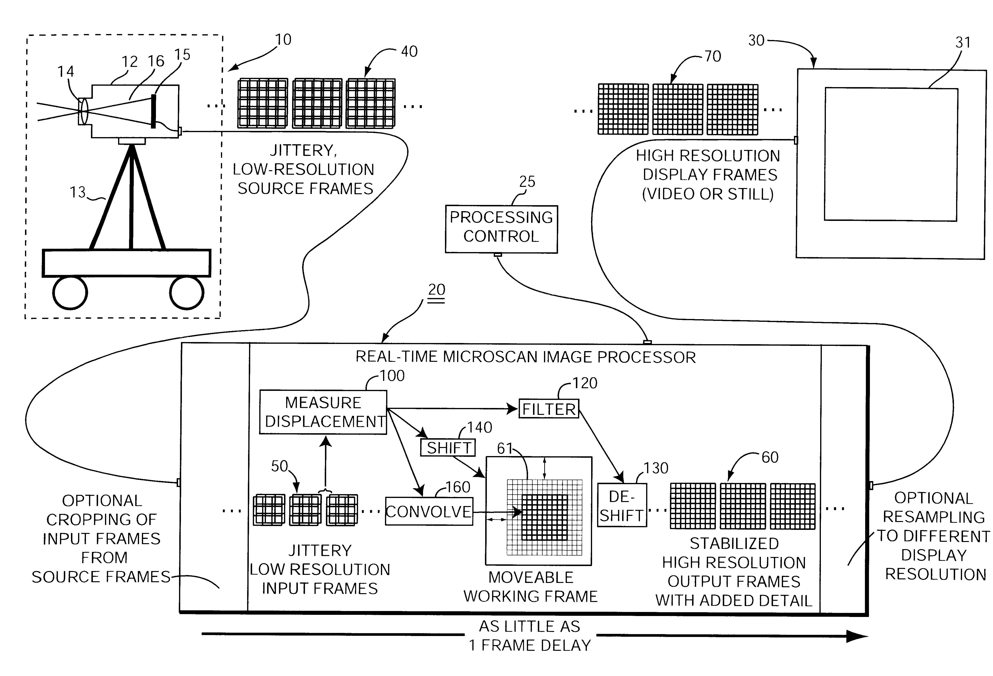
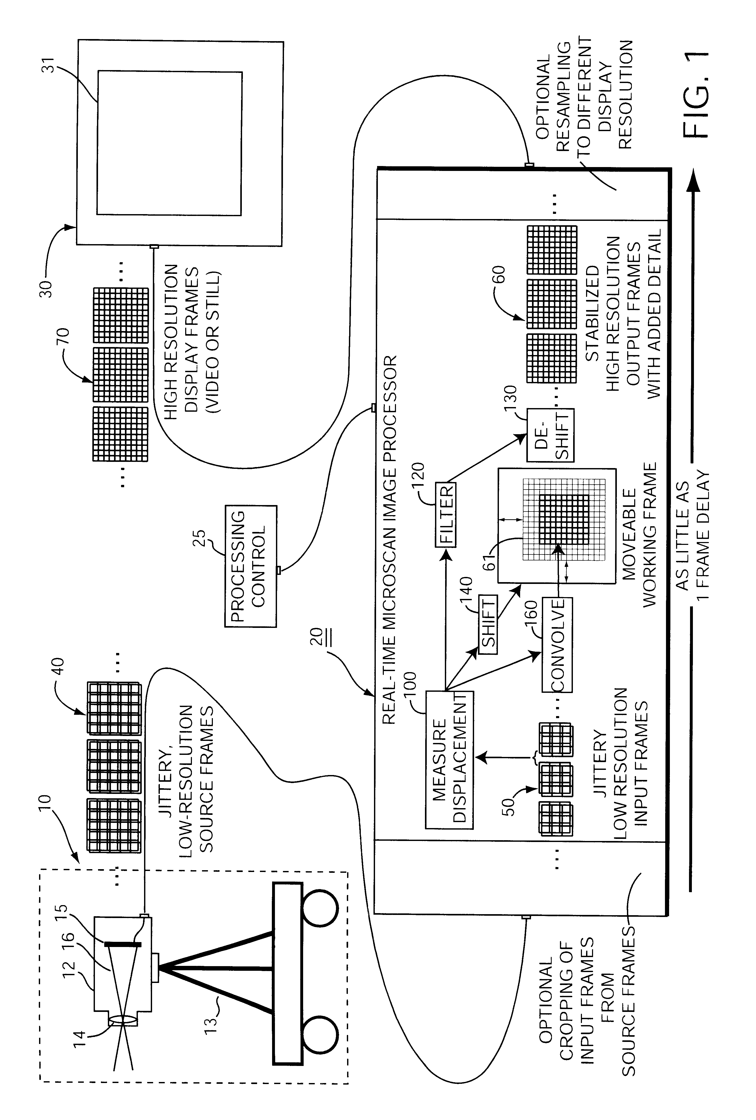
FIGS. 2-12 are directed to the presently preferred embodiment 20 that runs on a general purpose computer. This embodiment reads low-resolution source frames 40 from a data file, processes them, and ultimately outputs high-resolution display frames 70 to a display device 30. The computer, of course, is governed by suitable software. This software for this particular embodiment was written in "C", but any suitable programming language may be used. A complete copy of the source code is attached hereto as an Appendix.

Overview of Operation

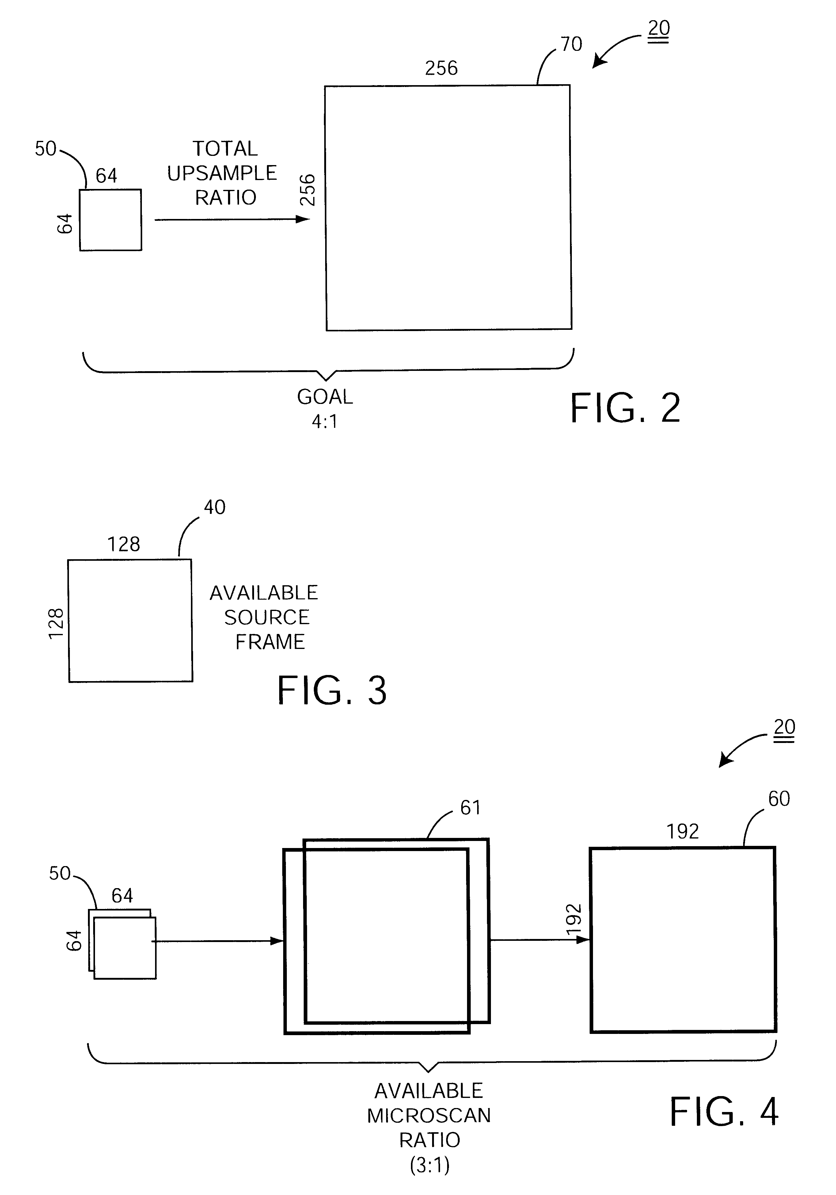
FIGS. 2-5 illustrate some developmental background that may be helpful in understanding certain idiosyncratic details of this embodiment.

FIGS. 5, 6, 7 and 8 offer conceptual views of how the preferred embodiment operates. Each one provides a successively more detailed abstraction of the preferred embodiment--progressing from the simple block diagram of FIG. 5, to the frame-centric version of FIG. 6, to the time-based diagram of FIG. 7, and finally to th...


PUM


Abstract

A method of processing low resolution input frames containing undersampled views of an optically imaged scene to produce a higher quality, higher resolution output frame. This method operates by obtaining a sequence of low resolution input frames containing different undersampled views of an optically imaged scene. With regard to each new low resolution input frame, the method involves the further steps of measuring a displacement between a previous low resolution input frame and a new low resolution input frame to sub-pixel precision to produce a measured displacement; coarsely registering a high resolution working frame with the new low resolution input frame based on the measured displacement; finely registering the new low resolution input frame with the high resolution working frame by expanding the new low resolution input frame into a new high resolution input frame based on the measured displacement; and merging the new high resolution input frame into the high resolution working frame to produce an output frame.

Description

1. Field of the InventionThe invention relates generally to digital image processing and, more particularly, to a method of using a sequence of low resolution that are subject to random jitter and contain undersampled features or scenes to produce one higher quality, higher resolution as a still image or to produce a sequence of such higher resolution frames as a video image.2. Discussion of Related ArtImages may be defined in terms of both "resolution" and "detail" with relevance to this invention. "Resolution" is a term that has taken on two different meanings in the image processing community. Strictly speaking, resolution refers to the number of pixels packed into a certain length or area. This application, however, uses resolution in the more general and perhaps more common sense, i.e. to refer to the sheer number of pixels in an image. Accordingly, one might regard a low resolution frame as a low pixel count frame (LPC frame) and a high resolution frame as a high pixel count f...

Claims


Application Information

Patent Timeline
Patent Type & Authority Patents(United States)
IPC IPC(8): G06T3/40H04N7/01H04N5/262H04N5/232H04N5/14
CPCG06T3/4069H04N5/14H04N7/0125H04N5/23254H04N5/23264H04N5/2624H04N5/23248H04N5/145H04N23/68H04N23/6811H04N23/682
Inventor CARLSON, RANDOLPH S.ARNOLD, JACK L.FELDMUS, VALENTINE G.
Owner NYTELL SOFTWARE LLC
Why Eureka
Try Eureka