Lane marker projection method for a motor vehicle vision system

a technology of vision system and lane marker, which is applied in the direction of process and machine control, distance measurement, instruments, etc., can solve the problem that dredging or periodic lane markers can have relatively large gaps

Active Publication Date: 2006-05-23
APTIV TECH LTD
View PDF28 Cites 130 Cited by
  • Summary
  • Abstract
  • Description
  • Claims
  • Application Information

AI Technical Summary

Problems solved by technology

However, dashed or periodic lane markers can have relatively large gaps, and frequently only a fraction of a lane marker is visible to the camera in any given video frame, particularly in mechanizations where a portion of the roadway within the video frame is obscured by the hood or fenders of the vehicle.

Method used


Image

  • Lane marker projection method for a motor vehicle vision system
  • Lane marker projection method for a motor vehicle vision system
  • Lane marker projection method for a motor vehicle vision system

Examples


Embodiment Construction

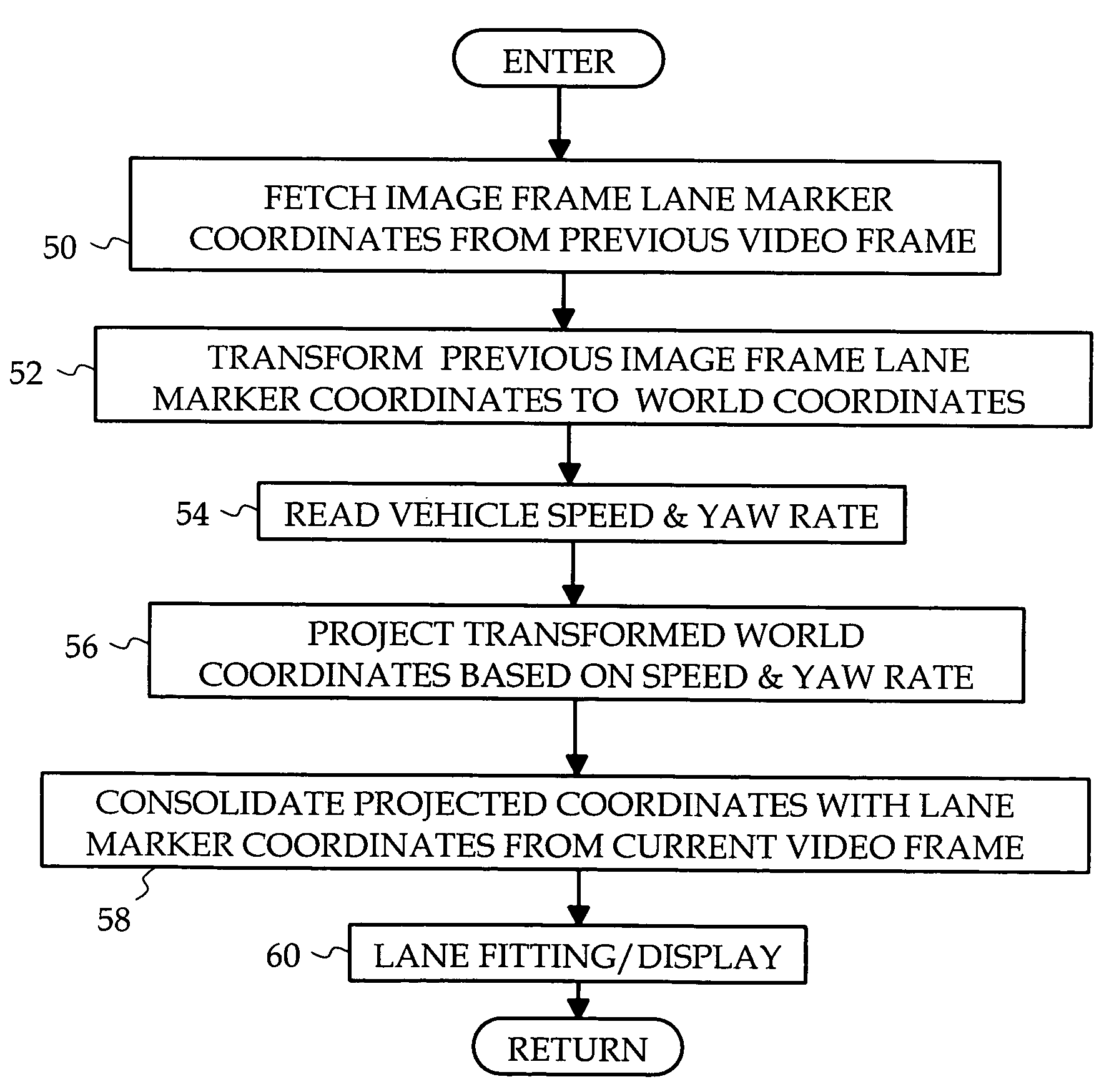
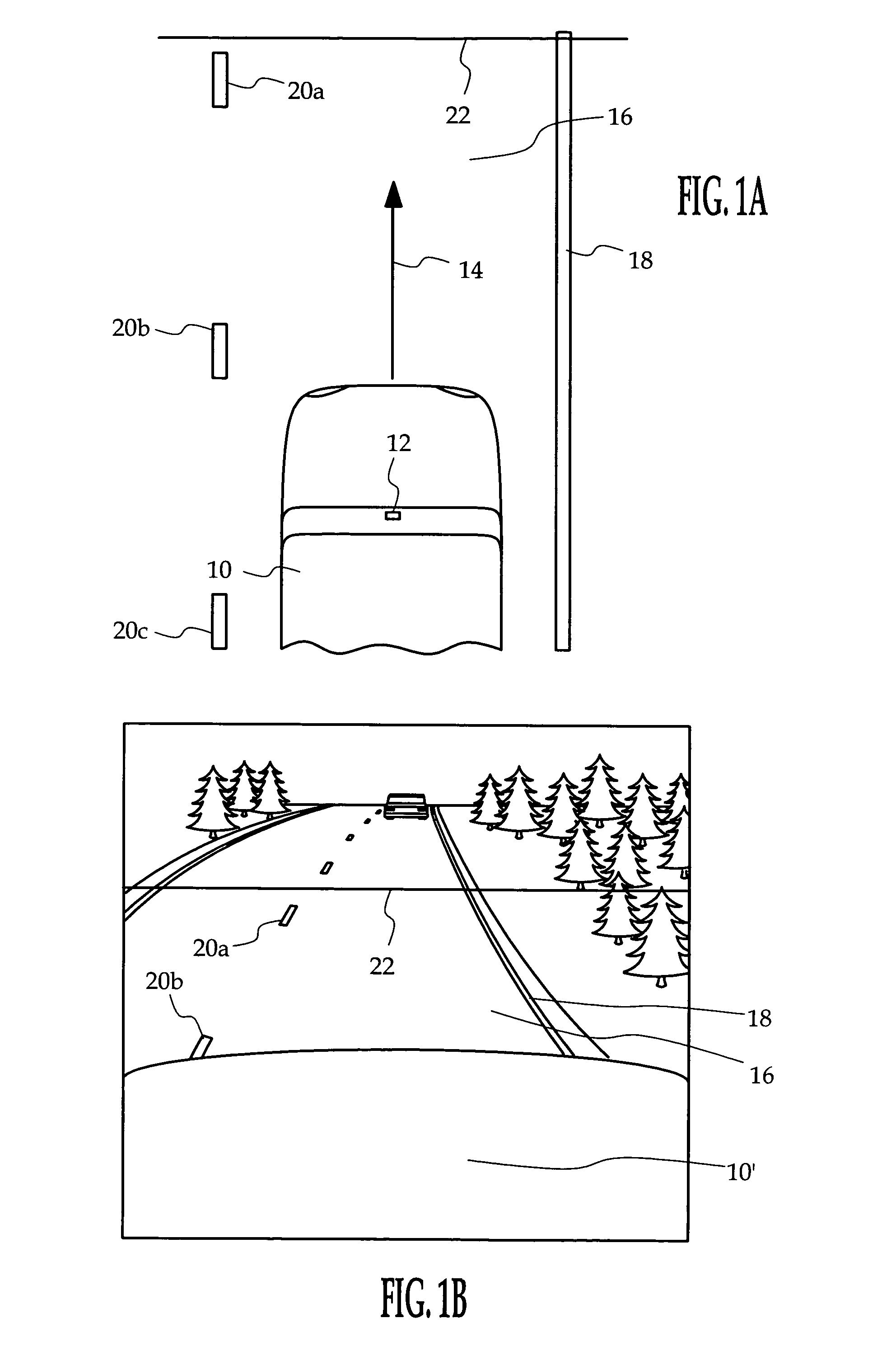
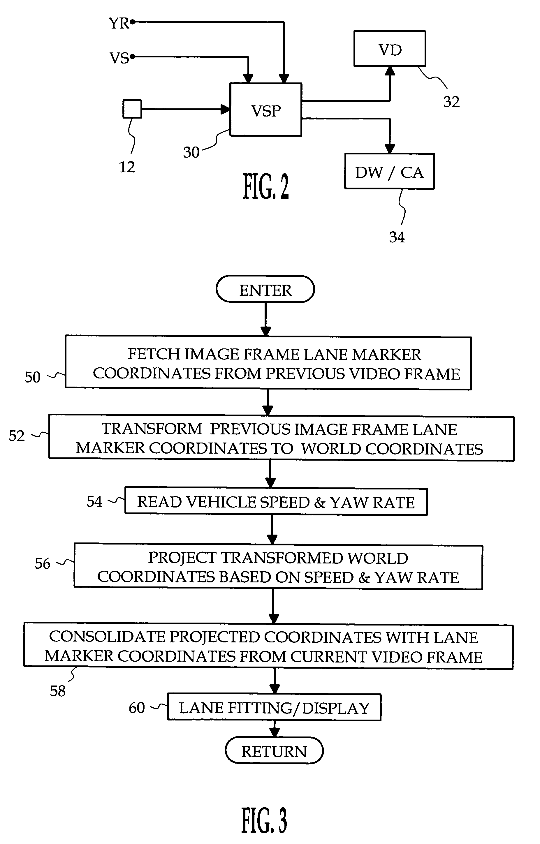
[0008]The method of the present invention is carried out in a vehicle-mounted vision system designed, among other things, to capture video images of a scene in the forward path of the vehicle for analysis and / or display to the driver. One of the principle objectives of the video image analysis is to identify lane markers painted on the roadway and the location of the host vehicle relative to the markers. FIG. 1A is a real world or overhead view of a host vehicle 10 equipped with a video camera 12 mounted in the passenger compartment, in the vicinity of an interior rearview mirror, for example. The vehicle 10 is traveling in the direction of arrow 14 down a two-lane roadway 16. The reference numeral 18 designates a continuous lane marker for the edge of roadway 16, and the reference numerals 20a, 20b, 20c designate center lane marker segments dividing the two lanes of roadway 16. FIG. 1B presents an image plane view forward of the vehicle 10 as seen by the camera 12. As illustrated i...


PUM


Abstract

Lane marker coordinate data obtained from a previous frame of a vehicle vision system is projected into the current video frame based on measured translation and rotation of the host vehicle. The projected lane marker coordinate data is consolidated with lane marker coordinate data from the current video frame for lane detection or display applications.

Description

TECHNICAL FIELD[0001]The present invention relates to motor vehicle vision system applications that track or display the location of the vehicle relative to roadway lane markers, and more particularly to a method of consolidating lane marker position information from successively generated video images.BACKGROUND OF THE INVENTION[0002]Motor vehicle forward vision data generated by a video camera mounted at or near the driver's eye level can be processed to identify various items of interest such as roadway lane markers. The vision system can then determine the location of the vehicle relative to the lane markers, for displaying video information to the driver or for detecting lane changing and / or driving patterns indicative of a drowsy driver. Most of these applications require lane marker detection in a region of about 5–30 meters forward of the vehicle, where the lane markers can be reliably approximated as straight lines. However, dashed or periodic lane markers can have relative...

Claims


Application Information

Patent Timeline
Patent Type & Authority Patents(United States)
IPC IPC(8): G06G7/78
CPCG06T7/2033G06T7/0042G06K9/00798B60T2201/08B60T2201/089G06T7/73G06T7/246G06V20/588
Inventor SCHWARTZ, DAVID A.HAMILTON, LISA R.
Owner APTIV TECH LTD
Why Eureka
Try Eureka