Prong Cage for an Angular Contact Ball Bearing and Method for Assembling an Angular Contact Ball Bearing

a technology of angular contact ball bearing and prong cage, which is applied in the direction of manufacturing tools, mechanical equipment, rotary machine parts, etc., can solve the problem that the present invention retainer does not provide a snap-fit about the ball elements

Inactive Publication Date: 2011-12-08
THE TIMKEN CO
View PDF2 Cites 14 Cited by
  • Summary
  • Abstract
  • Description
  • Claims
  • Application Information

AI Technical Summary

Problems solved by technology

However, in contrast to standard “crown” type snap-in retainers, the present invention retainer does not provide a snap fit about the ball elements.

Method used


Image

  • Prong Cage for an Angular Contact Ball Bearing and Method for Assembling an Angular Contact Ball Bearing
  • Prong Cage for an Angular Contact Ball Bearing and Method for Assembling an Angular Contact Ball Bearing
  • Prong Cage for an Angular Contact Ball Bearing and Method for Assembling an Angular Contact Ball Bearing

Examples


Embodiment Construction

[0022]The following detailed description illustrates the invention by way of example and not by way of limitation. The description enables one skilled in the art to make and use the present disclosure, and describes several embodiments, adaptations, variations, alternatives, and uses of the present disclosure, including what is presently believed to be the best mode of carrying out the present disclosure.

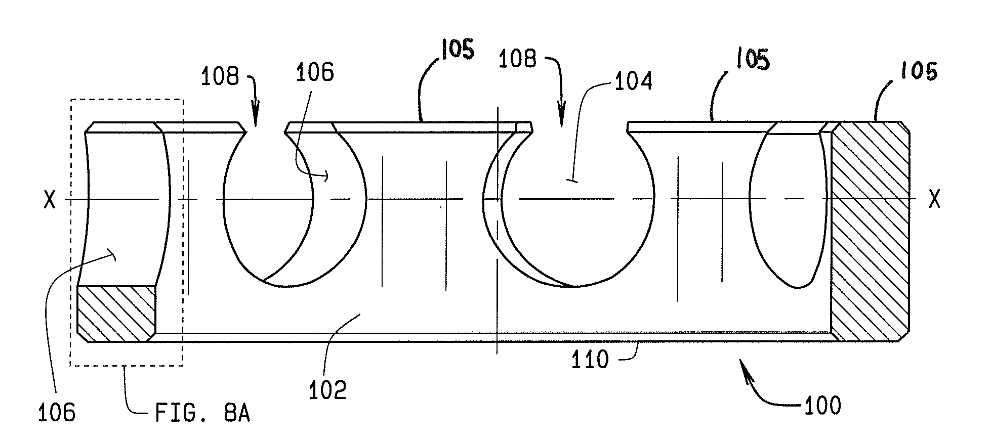
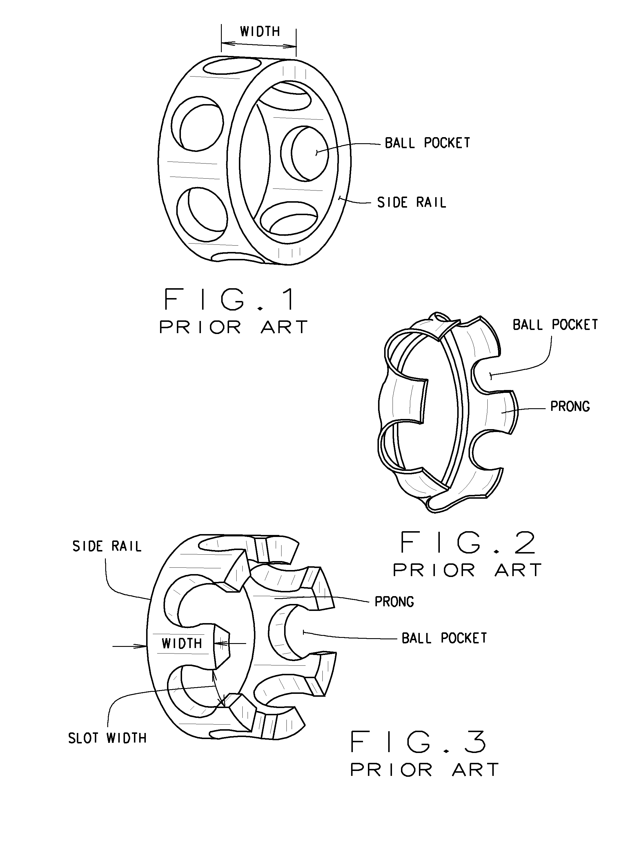
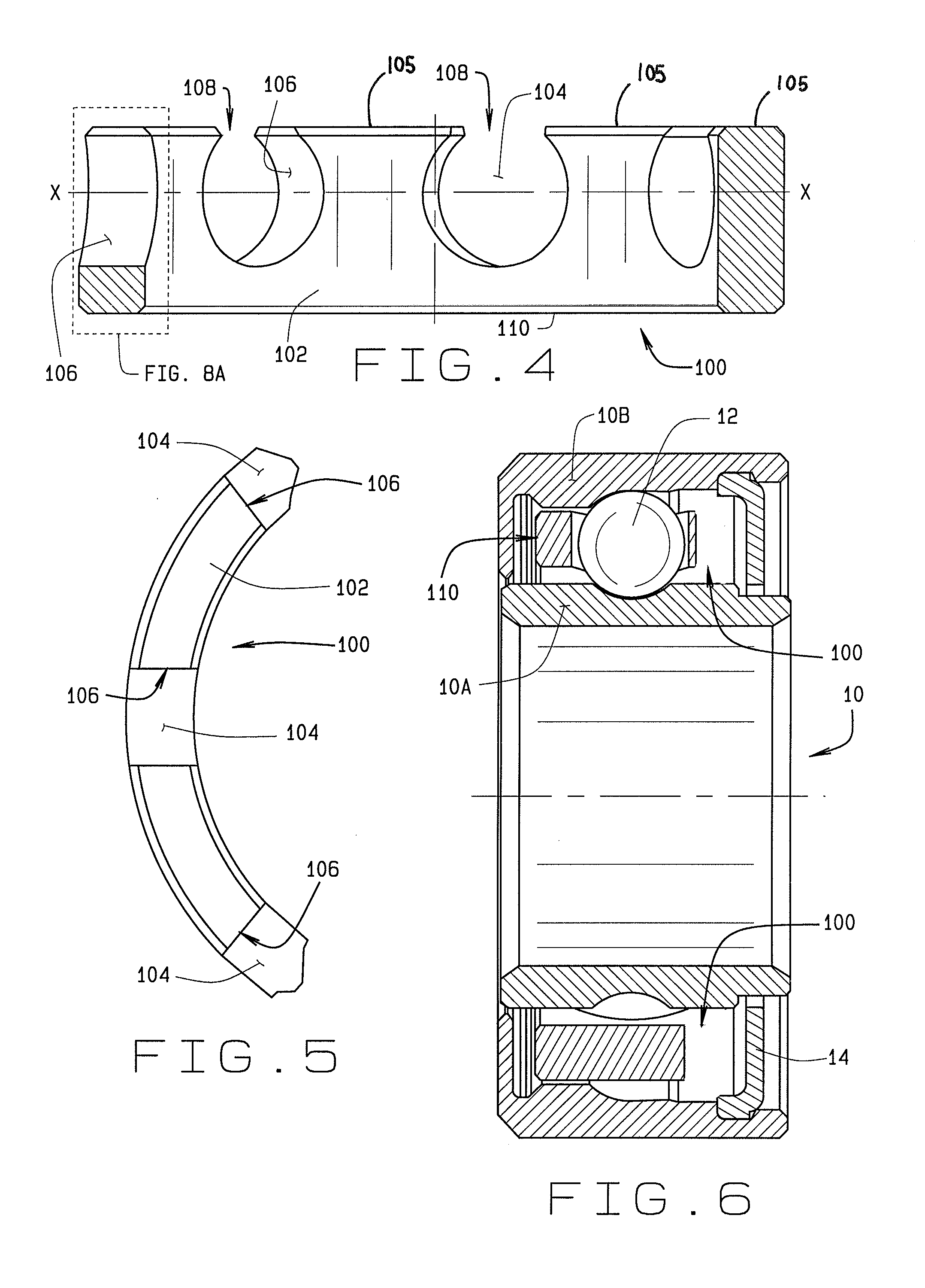
[0023]Turning to the Figures, and to FIGS. 4-6 in particular, an improved angular contact ball bearing retainer 100 of the present disclosure is shown to be different than both the traditional angular contact ball bearing (ACBB) retainers and the traditional stamped, machined, or molded crown-type and snap-in retainers. The preferred embodiment of the present disclosure is a cylindrical retainer body 102, with cylindrical ball pockets 104 arrayed around the circumference of the retainer body 102 as shown in FIG. 5. The axis X of each cylindrical ball pocket 104 intersects an axial c...


PUM

PropertyMeasurementUnit
circumferenceaaaaaaaaaa
widthaaaaaaaaaa
diameteraaaaaaaaaa

Abstract

An angular contact ball bearing cylindrical retainer element (100) with a reduced mass, reduced axial width, and a rigid “crown” shape. The rigid crown shape of the cylindrical retainer element (100) defines a plurality of uniformly spaced cylindrical ball receiving pockets (104) about the circumference of the cylindrical retainer (100), each receiving pocket partially open to a slot (108) on an axial end of the retainer (100) and enclosed at an opposite axial end to define a continuous axial side rail (110).

Description

CROSS-REFERENCE TO RELATED APPLICATIONS[0001]The present application is related to, and claims priority from, U.S. Provisional Patent Application Ser. No. 61 / 152,829 filed on Feb. 16, 2009, and which is herein incorporated by reference.STATEMENT REGARDING FEDERALLY SPONSORED RESEARCH[0002]Not Applicable.BACKGROUND OF THE INVENTION[0003]The present disclosure is related generally to small angular contact ball bearings, and in particular, to a small angular contact ball bearing for use in an application having only a limited axial space for a ball retainer.[0004]Within an angular contact ball bearing assembly, a traditional angular contact ball bearing (ACBB) retainer, such as shown in FIG. 1, is an annular structure which protrudes past both sides of, or completely surrounds, the ball elements which are disposed within openings about the circumference of the structure. An alternative configuration, known as a crown retainer, is shown in FIGS. 2 and 3, and protrudes past only one side...

Claims


Application Information

Patent Timeline
Patent Type & Authority Applications(United States)
IPC IPC(8): F16C33/38B23P11/00
CPCF16C19/163F16C33/414Y10T29/4968F16C2300/12F16C43/04
Inventor DAMATO, FRANK J.SANVILLE, JAMES M.
Owner THE TIMKEN CO
Why Eureka
Try Eureka