Eureka AIR delivers breakthrough ideas for toughest innovation challenges, trusted by R&D personnel around the world.

Wire fastening band

a fastening band and wire technology, applied in the direction of snap fasteners, magnets, magnetic bodies, etc., can solve the problems of tripping, fracture of inner wires, and inability to be pretty, and achieve the effect of fast and convenient different friction force, and easy sheathing on the wir

Inactive Publication Date: 2011-12-22
WANG WANG DAH ENTERPRISE
View PDF13 Cites 40 Cited by
  • Summary
  • Abstract
  • Description
  • Claims
  • Application Information

AI Technical Summary

Benefits of technology

[0005]The primary object of the present invention is to provide a wire fastening band which can be sheathed on the wire quickly and conveniently, and can wrap and fix the wound wire, such that the wire will not be dropped out or intertwined.
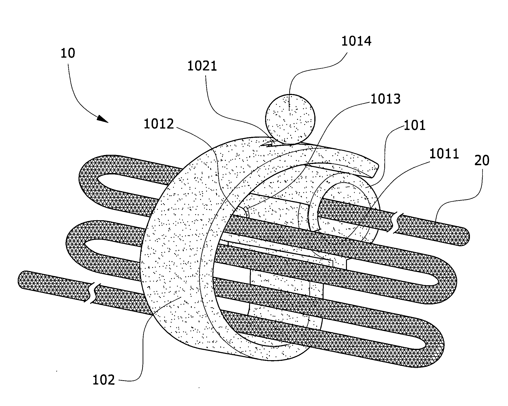
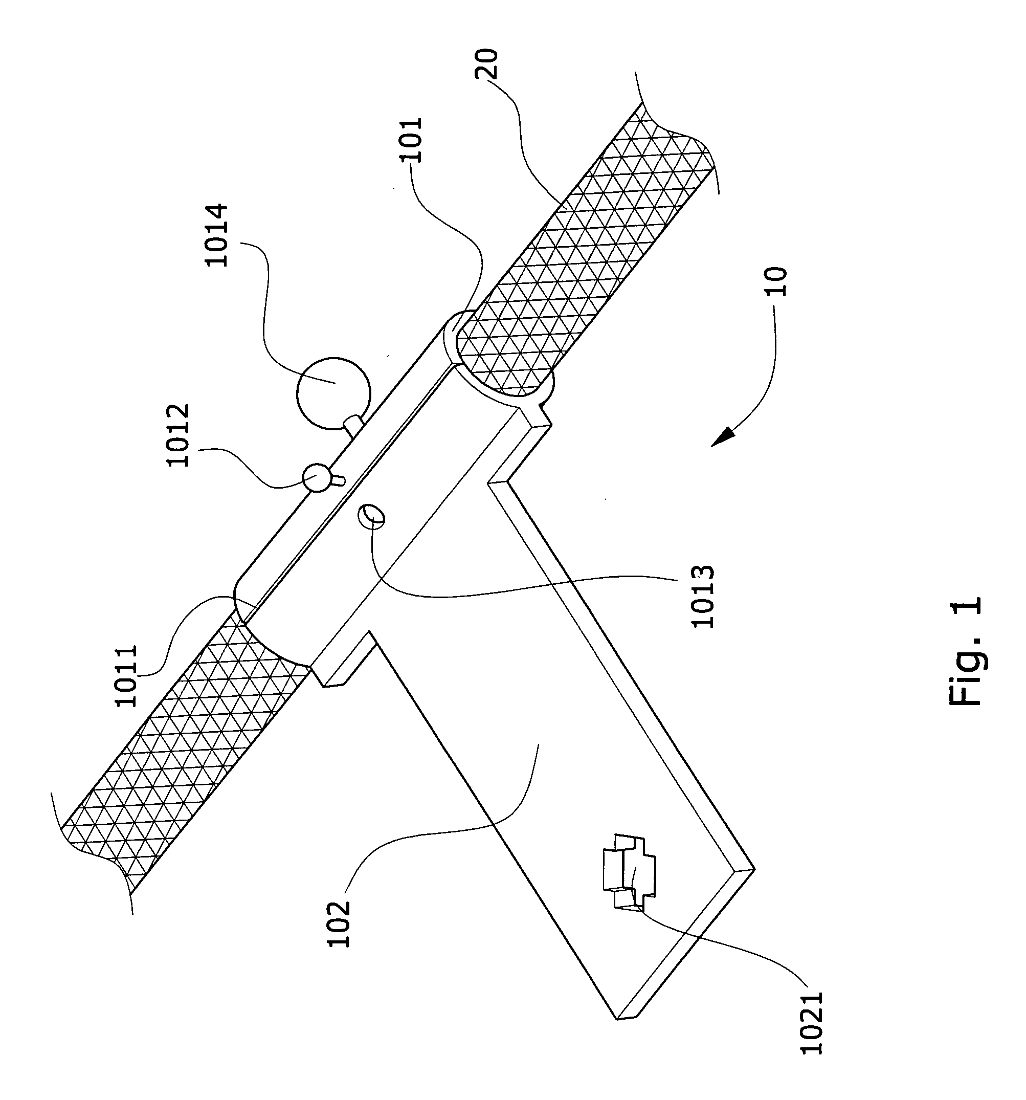
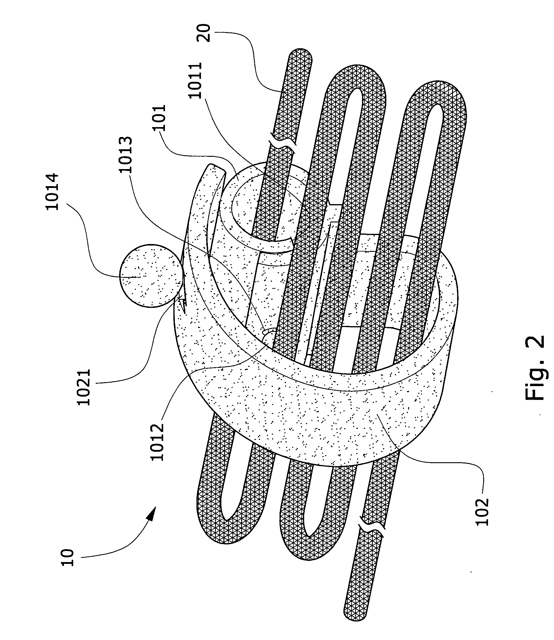
[0006]Accordingly, a wire fastening band of the present invention includes a first fastening member, a second fastening member, a first corresponding fastening member, a second corresponding fastening member, a wrapping member, and a sleeve. When a wire is sheathed into the sleeve through a commissure formed on the sleeve, the wire fastening band can freely slide on the wire using features that the wire fastening band is provided with a different material and a different friction force than the wire. In addition, by the formation of the commissure, the wire fastening band can be easily sheathed on the wire. On the other hand, an upper end of the sleeve are formed with the first fastening member and the second fastening member, and a lower end of the sleeve is extendedly formed with the wrapping member, an end of which are formed with the first corresponding fastening member and the second corresponding fastening member. When the first corresponding fastening member is fastened with the first fastening member, the sleeve will wrap and fix the wire; whereas, when the second corresponding fastening member is fastened with the second fastening member, the wrapping member will wrap the wire, such that the wire fastening band can be sheathed on the wire quickly and conveniently, and the entire wound wire can be wrapped without being dropped out or intertwined.

Problems solved by technology

In using the electrical appliances, the wires which are exposed out of the appliances will be intertwined, easily resulting in a danger of being tripped when a user passes by, and being not pretty either.
In addition, when the appliances are collected after being used, as the user seldom knows how to collect the wires, the wires are always wound on articles, tied up casually, or left alone without taking care of.
Therefore, if the appliances are to be used next time, in addition to that time must be wasted to unwind the intertwined wires, when the wires are intertwined, it is easy to result in fracture to inner wirings of the wires due to excessive distortion, thereby easily causing damage to the articles.

Method used


Image

  • Wire fastening band
  • Wire fastening band
  • Wire fastening band

Examples


second embodiment

[0016]Referring to FIG. 3, it shows a schematic view of the present invention, wherein a wire fastening band 30 is integrally formed by a soft rubber, and includes a sleeve 301 after being formed. A circumferential surface of the sleeve 301 is formed with a commissure 3011, and an outer circumferential surface of the sleeve 301 is extendedly formed with a wrapping member 302. As shown in the drawing again, above the sleeve 301 is attached with a first Velcro tape 3012 (or a magnet), and at a corresponding position in an interior side of the sleeve 301 is also attached with a first corresponding Velcro tape 3013 (or a magnet). At a position close to a top of the first Velcro tape 3012 is formed with a first fastening member 3014, and a corresponding position on a plane of the wrapping member 302 is formed with a first corresponding fastening member 3021. Upon implementing, the sleeve 301 is first sheathed on a wire 20 (such as an earphone wire or a power cable) with the commissure 30...

third embodiment

[0017]Referring to FIG. 4, it shows a schematic view of the present invention, wherein a wire fastening band 40 is integrally formed by a soft rubber and includes a sleeve 401 after being formed. A circumferential surface of the sleeve 401 is formed with a commissure 4011, and an outer circumferential surface of the sleeve 401 is extendedly formed with a wrapping member 402. As shown in the drawing again, above the sleeve 401 is formed with a first fastening member 4012, at a corresponding position in an interior side of the sleeve 401 is attached with a first corresponding fastening member 4013, at a position close to a top of the first fastening member 4012 is attached with a first Velcro tape 4014 (or a magnet), and at a corresponding position on a plane of the wrapping member 402 is also formed with a first corresponding Velcro tape 4021 (or a magnet). Upon implementing, the sleeve 401 is first sheathed on a wire 20 (such as an earphone wire or a power cable) with the commissure...

fourth embodiment

[0018]Referring to FIG. 5, it shows a schematic view of the present invention, wherein a wire fastening band 50 is integrally formed by a soft rubber and includes a sleeve 501 after being formed. A circumferential surface of the sleeve 501 is also formed with a commissure 5011, and an outer circumferential surface of the sleeve 501 is extendedly formed with a wrapping member 502. As shown in the drawing again, above the commissure 5011 of the sleeve 501 are attached with a first Velcro tape 5012 (or a magnet) and a second Velcro tape 5014 (or a magnet), below the commissure 5011 is attached with a first corresponding Velcro tape 5013, and at a corresponding position on a plane of the wrapping member 502 is attached with a second corresponding Velcro tape 5021 (or a magnet). Upon implementing, the sleeve 501 is first sheathed on a wire 20 (such as an earphone wire or a power cable) with the commissure 5011, and then the first Velcro tape 5012 is affixed with the first corresponding V...


PUM

PropertyMeasurementUnit
friction forceaaaaaaaaaa
flexibilityaaaaaaaaaa
forceaaaaaaaaaa

Abstract

A wire fastening band is made by a soft material and can be sheathed on a wire by using a commissure formed on a sleeve. The sleeve is extended with a wrapping member to fix and fasten the collected wire. The sleeve on the wire is also formed with a first fastening member, a second fastening member, and a first corresponding fastening member. The first fastening member is fastened with the first corresponding fastening member to fix the sheathed wire, and then the second fastening member is fastened with a second corresponding fastening member on the wrapping member to quickly and conveniently fix and fasten the collected wire.

Description

BACKGROUND OF THE INVENTION[0001]a) Field of the Invention[0002]The present invention relates to a wire fastening band used to fix a wire that has been wound, and more particularly to a wire fastening band which can be sheathed on the wire quickly and conveniently, and can fix the wire that has been wound, such that the wire will not be dropped out or intertwined.[0003]b) Description of the Prior Art[0004]It is known that some of daily articles in an everyday life are usually added with some wires; for example, an ordinary household electrical appliance will be equipped with an electric cable, and an earphone will have a wire. In using the electrical appliances, the wires which are exposed out of the appliances will be intertwined, easily resulting in a danger of being tripped when a user passes by, and being not pretty either. In addition, when the appliances are collected after being used, as the user seldom knows how to collect the wires, the wires are always wound on articles, t...

Claims


Application Information

Patent Timeline
Patent Type & Authority Applications(United States)
IPC IPC(8): F16G11/02H01F7/02A44B18/00
CPCB65D63/1027B65D2313/02B65D2313/04Y10T24/2708H01F7/0263Y10T24/32Y10T24/398H04R1/1033
Inventor SUN, WEN-WEI
Owner WANG WANG DAH ENTERPRISE
Why Eureka
Eureka Blog
Learn More