Welding wire retraction system and method

a technology of retraction system and welding wire, which is applied in the field of welding systems, can solve the problems of reducing welding efficiency, welding wire being too far out of the torch, and welding wire being wasted

Active Publication Date: 2011-12-22
ILLINOIS TOOL WORKS INC
View PDF2 Cites 17 Cited by
  • Summary
  • Abstract
  • Description
  • Claims
  • Application Information

AI Technical Summary

Benefits of technology

In an exemplary embodiment, a welding torch includes a handle configured to receive welding wire from a wire source and to direct the welding wire to a torch tip. The welding torch also includes a first switch coupled to the handle and configured to cause the welding wire to

Problems solved by technology

Unfortunately, quite commonly more welding wire than desired may be provided to the welding torch causing the welding wire to extend too far out of the torch, such as if

Method used


Image

  • Welding wire retraction system and method
  • Welding wire retraction system and method
  • Welding wire retraction system and method

Examples


Embodiment Construction

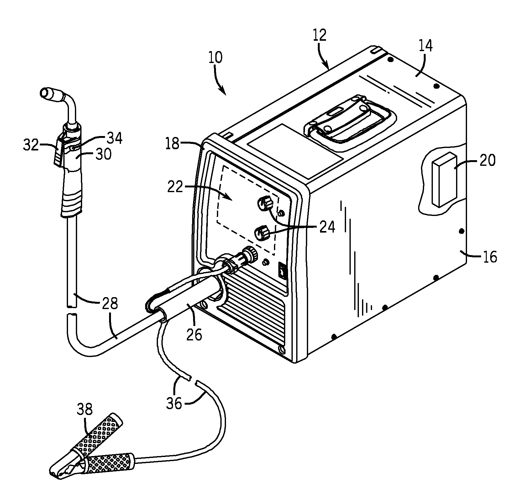
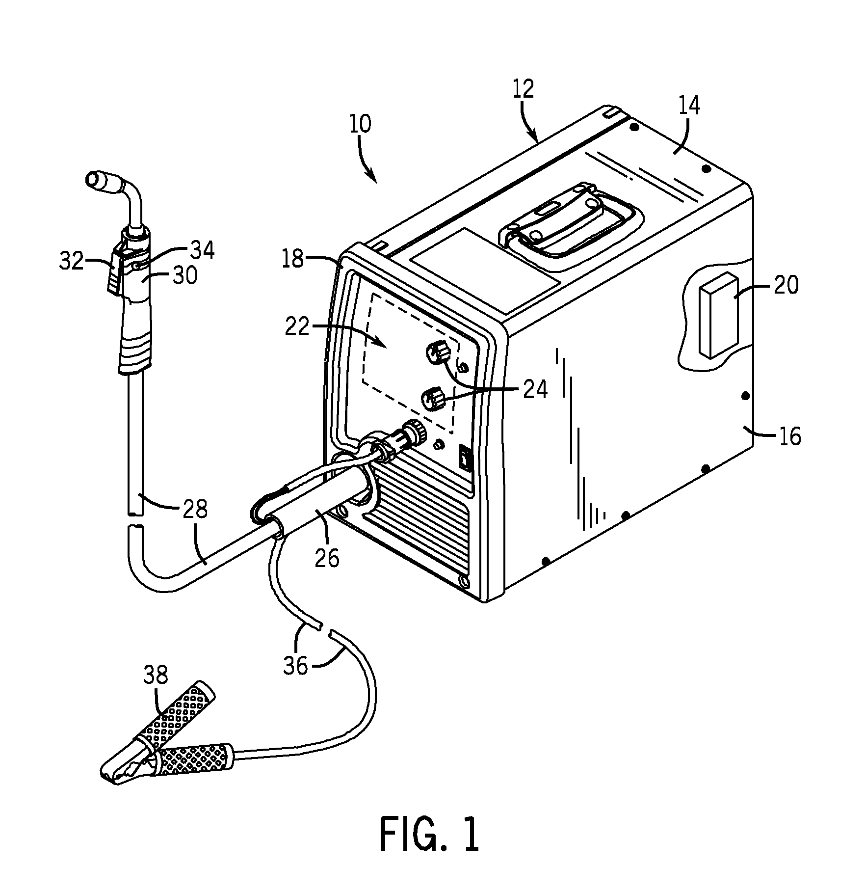
Turning now to the drawings, FIG. 1 is a perspective view of an exemplary welding power supply 10 configured for use in a gas metal arc welding (GMAW) process or a flux cored arc welding (FCAW) process. The welding power supply 10 includes a housing 12 including a top panel 14, a side panel 16, and a front panel 18. The top panel 14 may include a handle that facilitates transport of the welding power supply 10 from one location to another by an operator if desired. The side panel 16 includes a breakaway view illustrating a controller 20 configured to control operation of the welding power supply 10. The front panel 18 includes a control panel 22 adapted to allow an operator to set one or more parameters of the welding process, for example, via knobs 24 (or buttons, touchscreens, etc.).

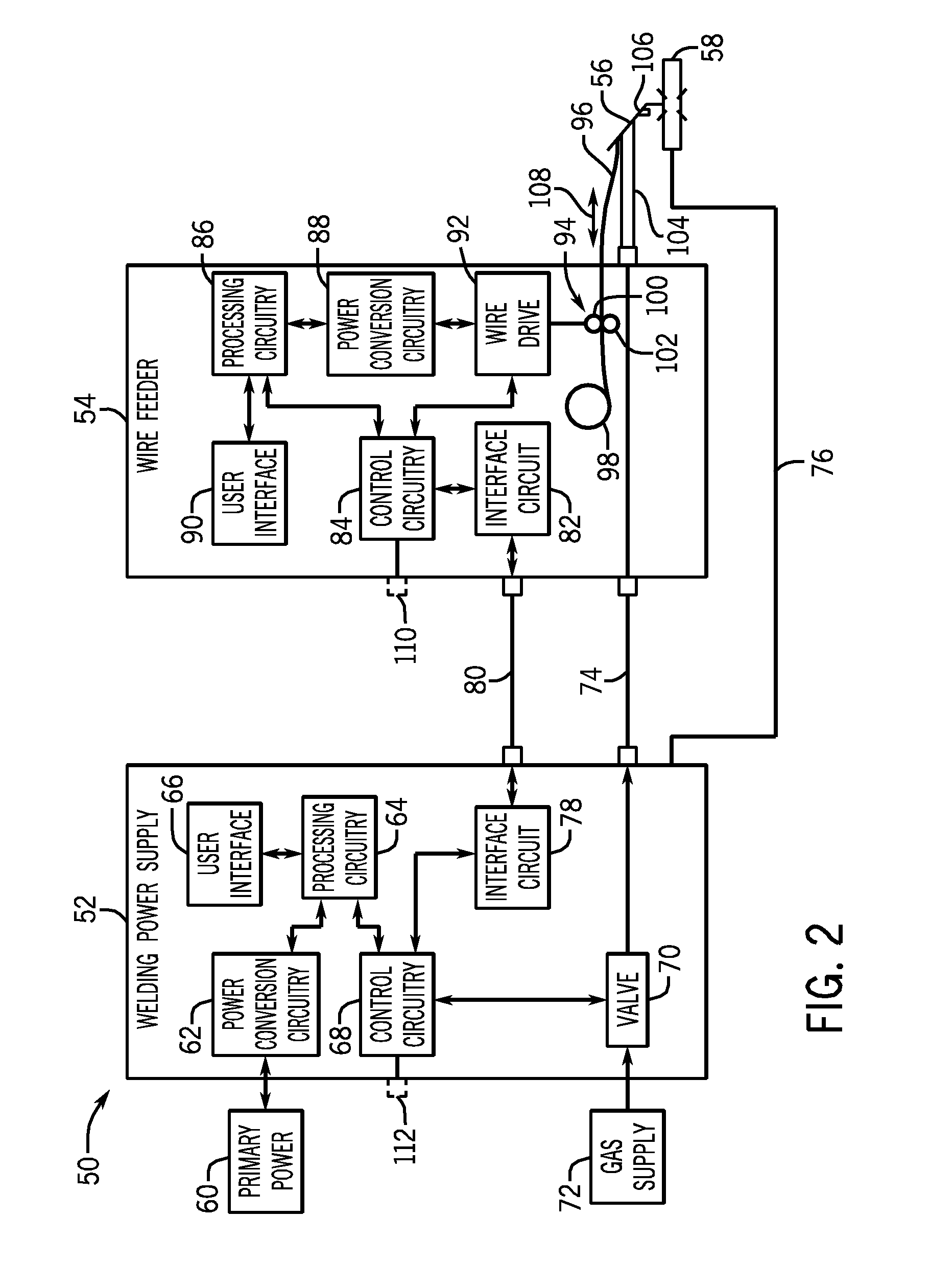
In certain embodiments, the welding power supply 10 includes the functionality of a wire feeder (i.e., internal wire feeder). Such embodiments may include a wire drive configured to receive control sig...


PUM

PropertyMeasurementUnit
Timeaaaaaaaaaa
Poweraaaaaaaaaa

Abstract

A method and system for retracting welding wire is provided. One welding torch includes a handle configured to receive welding wire from a wire source and to direct the welding wire to a torch tip. The welding torch also includes a first switch coupled to the handle and configured to cause the welding wire to extend out of the torch tip to expose more wire when the first switch is actuated. The welding torch includes a second switch coupled to the handle and configured to cause the welding wire to retract into the torch tip to expose less wire when the second switch is actuated.

Description

BACKGROUNDThe invention relates generally to welding systems and, more particularly, to a method and system for retracting welding wire in a welding system.Welding is a process that has become increasingly ubiquitous in various industries and applications. Such processes may be automated in certain contexts, although a large number of applications continue to exist for manual welding operations. In both cases, such welding operations rely on a variety of types of equipment to ensure that the supply of welding consumables (e.g., wire feed, shielding gas, etc.) is provided to the weld in an appropriate amount at the desired time. For example, metal inert gas (MIG) welding typically relies on a wire feeder to enable a welding wire to reach a welding torch, the wire being continuously fed during welding to provide filler metal and to ensure that arc heating is available to melt the filler metal and the underlying base metal.In MIG welding applications, the wire feeder typically provides...

Claims


Application Information

Patent Timeline
IPC IPC(8): B23K9/10B23K9/26
CPCB23K9/125B23K9/295B23K9/1336
Inventor ROZMARYNOWSKI, SCOTT RYANKRISHER, CALEB ROBERT
Owner ILLINOIS TOOL WORKS INC
Why Eureka
Try Eureka