Drawer latch

a technology for latches and drawers, applied in the field of drawer latches, can solve the problems of increased number of parts, inoperable drawers, and high cos

Active Publication Date: 2011-12-22
QUALITY CRAFT INDS
View PDF5 Cites 70 Cited by
  • Summary
  • Abstract
  • Description
  • Claims
  • Application Information

AI Technical Summary

Benefits of technology

[0028]Although it has been discussed herein that the arrangement is directed to a mechanic's tool cab

Problems solved by technology

Although this is a useful arrangement, the drawer catches are positioned within the interior volume of the drawer which, can lead to breakage of the catch or bending of the catch which would therefore render the drawer inoperative.
The system is effective, however, it is somewhat limited in that in the event that the drawer handle becomes da

Method used


Image

  • Drawer latch
  • Drawer latch
  • Drawer latch

Examples


Embodiment Construction

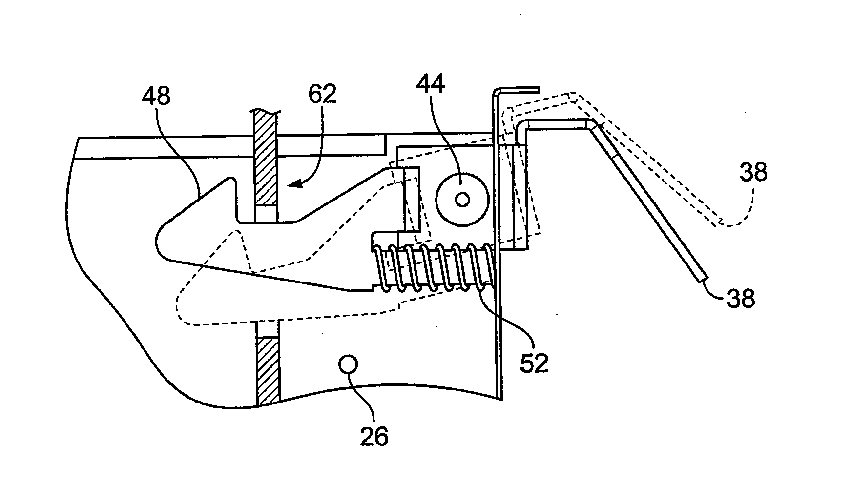
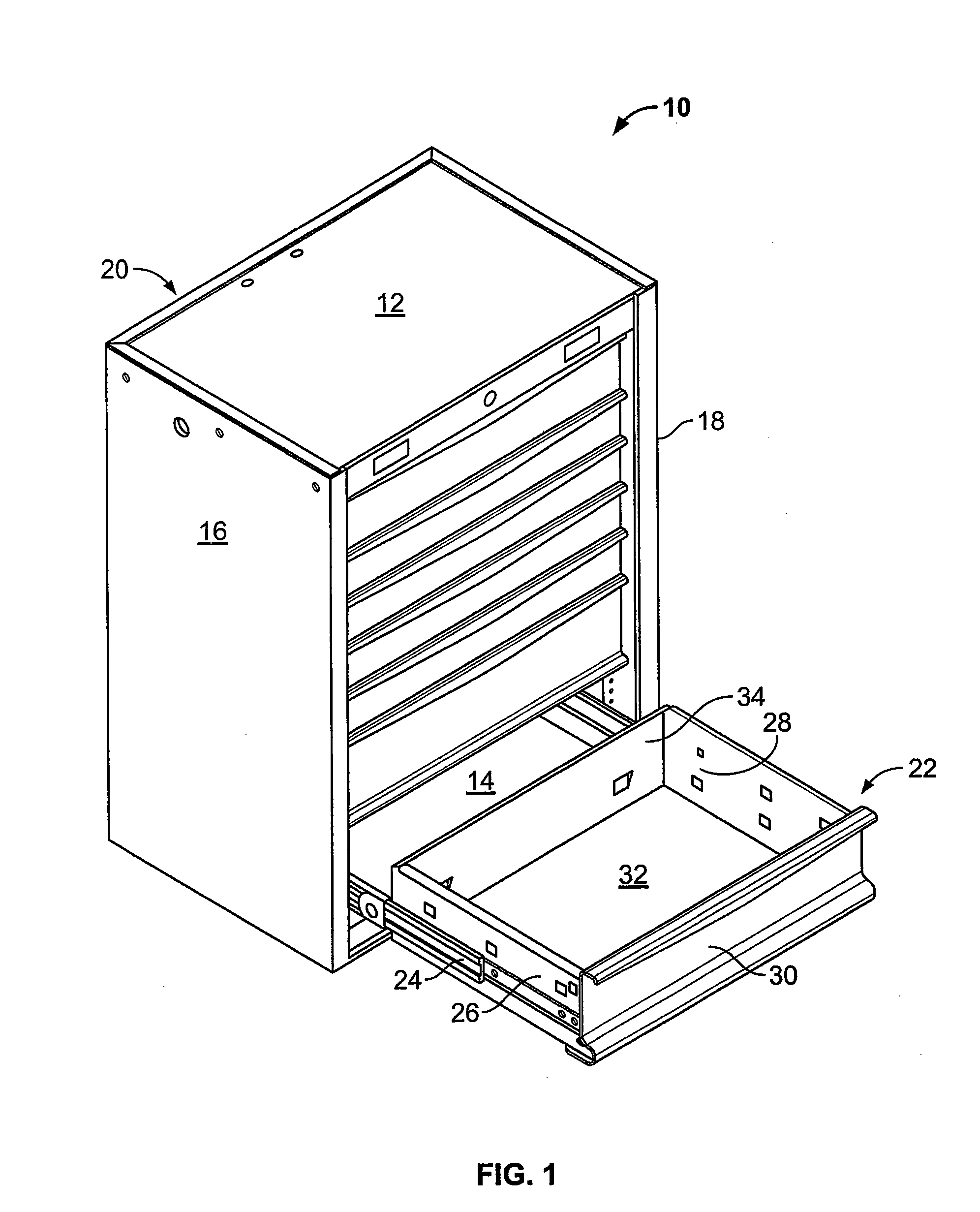
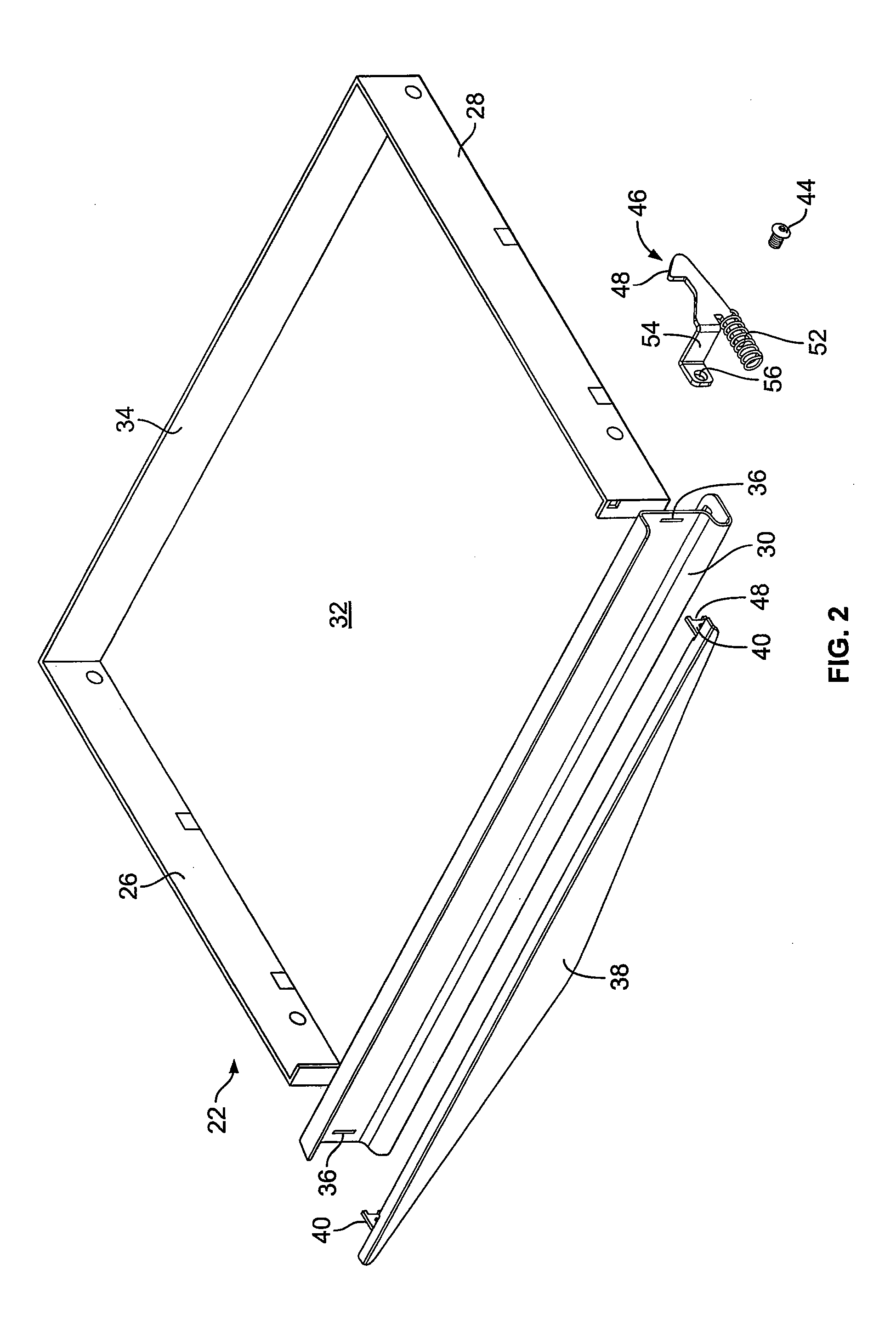
[0048]Referring now to FIG. 1, numeral 10 denotes a typical chest of drawers, typically used for the storage of tools. The chest includes a cabinet frame having a top 12, bottom 14, opposed side walls 16 and 18, respectively, and a back wall, generally denoted by numeral 20. As is well known, the individual drawers, generally denoted by numeral 22 have telescopic slides 24 attached to sides 26 and 28, respectively. Only one telescopic slide 24 is shown in FIG. 1. It will be understood that side 28 of drawer 22 includes a similar slide 24. The drawers each include a front wall 30, base wall 32 and back wall 34 as is typical most of these arrangements. Turning to FIG. 2, shown is more details concerning the nature of the present invention. The telescopic slides 24 have been removed from the illustration of the drawer 22 for purposes of the clarity.

[0049]In FIG. 2, front wall 30 of drawer 22 includes spaced apart apertures 36, an aperture of which is associated with opposite side of fr...


PUM


Abstract

A drawer latch assembly. The assembly provides a catch member which is mechanically connected but a separate component from the drawer handle. The drawer handle and catch operate in a concerted pivoting motion and pivot about a common fastener. The drawer handle provides a pair of arms which extend through the front wall of the drawer and have terminal end portions which include the cut out segment which locates and receives a portion of the latch member. In this manner the latch and terminal end portions of the arms are keyed together which alleviates stress on the pivot point and allows for easy repair of the arrangement in the event that either the handle or the catch become damaged.

Description

TECHNICAL FIELD[0001]The present invention relates to a drawer latch and more particularly, the present invention relates to an improved drawer latch having a key like receiving member for receiving a catch.BACKGROUND OF THE INVENTION[0002]It is well established that there are a number of drawer latches which have been established in the art previously. In the instant situation, the latch is particularly directed towards tool cabinets Such tool cabinets are known as mechanics' tool cabinets and typically have telescopic slides for the drawers with a cabinet formulated out of, for example, sheet metal. These cabinets often include a lock mechanism to prevent unauthorized access to the cabinet. In recent years the cabinets have become even more elaborate with the addition of lighting, power bars and other accessories.[0003]In terms of the latch systems that have been set forth for such cabinets, in United States re issued Pat. No. US RE 40,267, reissued Apr. 29, 2008, Mehmen discloses...

Claims


Application Information

Patent Timeline
IPC IPC(8): A47B88/04E05C3/14A47B95/02
CPCE05B1/00E05C3/14E05B65/46Y10T292/1092
Inventor RETCHLOFF, BARRYCHEN, RUNZHAO
Owner QUALITY CRAFT INDS
Why Eureka
Try Eureka