LED light source

Inactive Publication Date: 2011-12-22
OSRAM SYLVANIA INC
View PDF4 Cites 19 Cited by
  • Summary
  • Abstract
  • Description
  • Claims
  • Application Information

AI Technical Summary

Benefits of technology

[0008]The structure is simple and effi

Problems solved by technology

A seemingly ready contributor for such replacement has been the use of light emitting diodes: however, while the efficacy of LEDs has improved greatly over the last few years, the higher cost of these light sources, when employed to provide equivalent light to the incandescent sources, has prevented their use as a genera

Method used


Image

  • LED light source
  • LED light source
  • LED light source

Examples


Example

[0011]For purposes of this application it is to be understood that when an element or layer is referred to as being “on,”“connected to” or “coupled to” another element or layer, it can be directly on, connected to or coupled to the other element or layer or intervening elements or layers may be present. In contrast, when an element is referred to as being “directly on,”“directly connected to” or “directly coupled to” another element or layer, there are no intervening elements or layers present. Like numbers refer to like elements throughout. The term “and / or” includes any and all combinations of one or more of the associated listed items.

[0012]Although the terms “first,”“second,”“third” etc. may be used to describe various elements, components, regions, layers and / or sections, these elements, components, regions, layers and / or sections are not to be limited by theses terms as they are used only to distinguish one element, component, region, layer or section from another element, com...


PUM

PropertyMeasurementUnit
Electrical conductivityaaaaaaaaaa
Electrical conductoraaaaaaaaaa
Symmetryaaaaaaaaaa

Abstract

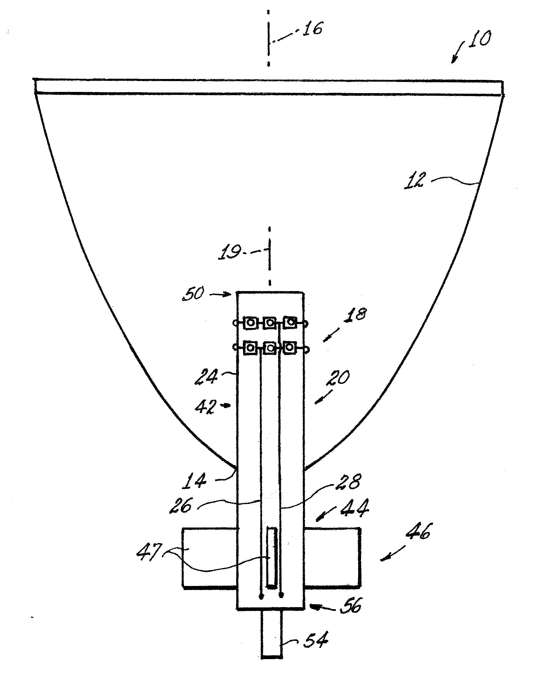
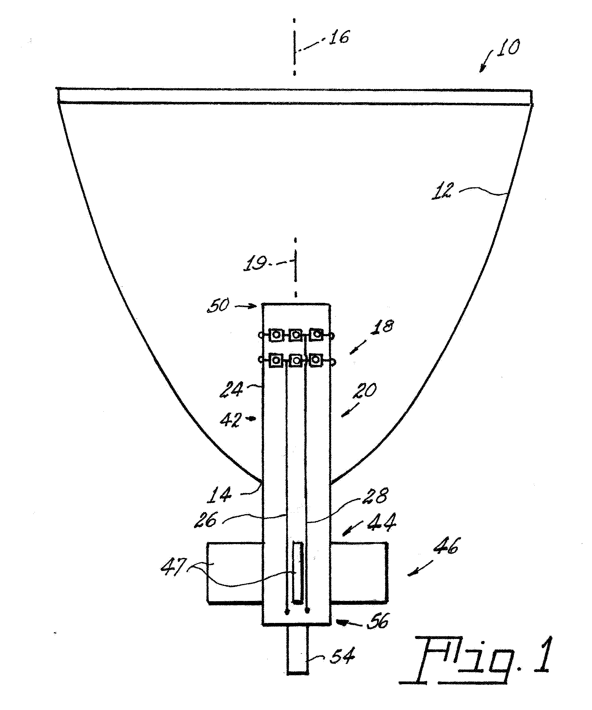
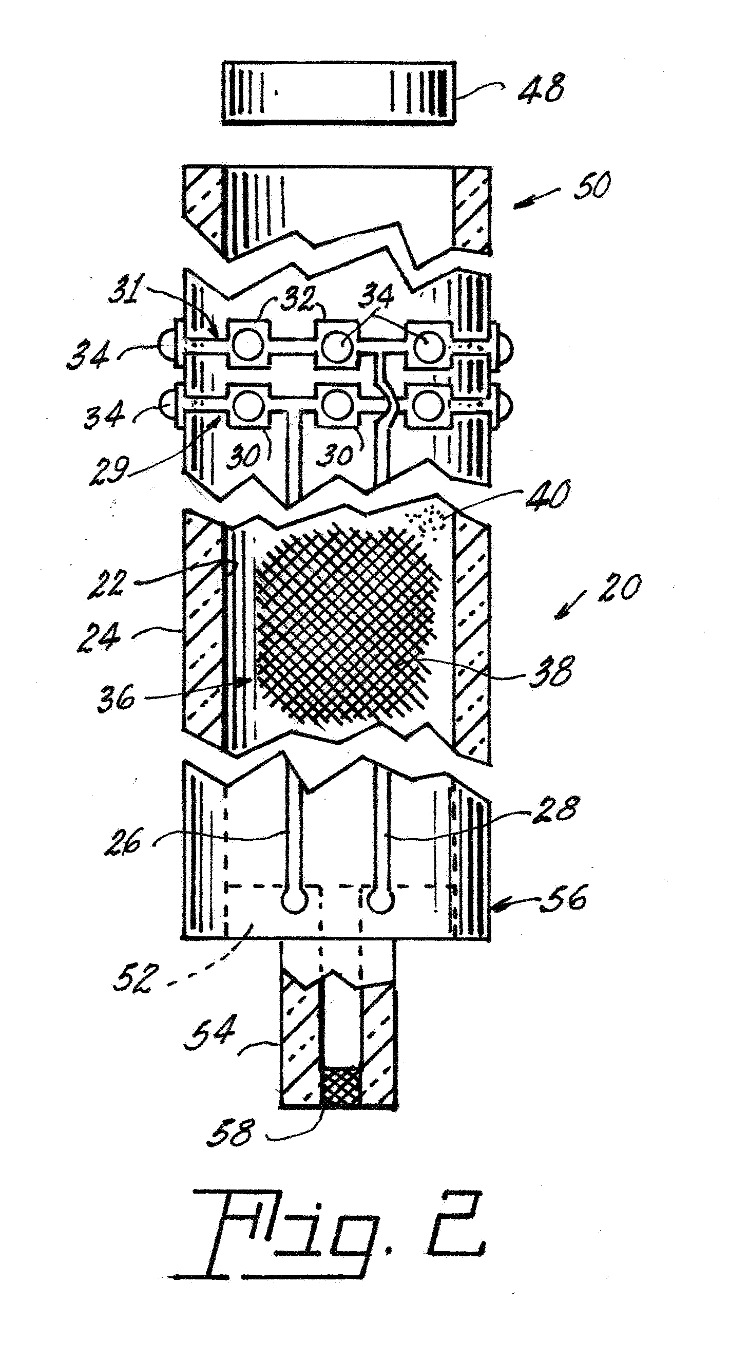
A lamp (10) has a concave reflector (12) that includes an opening (14) in the bottom thereof and is substantially symmetrically arrayed about a longitudinal axis (16). A light source (18) is positioned in the opening (14) and has a symmetry axis (19) that is coaxial with the longitudinal axis (16) of the reflector (12). The light source (18) comprises a hollow ceramic member (20) with an inner surface (22) and an outer surface (24). First and second electrically conductive traces (26, 28) and first and second rows (29, 31) of first and second electrically conductive pads (30, 32) connected by the electrically conductive traces (26, 28) are formed on the outer surface (24). Light emitting diodes (34) are associated with at least some of the electrically conductive pads (30, 32); and a heat-conducting mechanism (36) is contained within the hollow ceramic member (20) for removing heat generated by the light emitting diodes (34) when the light emitting diodes (34) are operating.

Description

TECHNICAL FIELD[0001]This invention relates to lamps and to light sources therefor. Still more particularly it relates to such lamps and light sources employing light emitting diodes (LED or LEDs)BACKGROUND ART[0002]The need for a replacement for the notoriously energy-inefficient incandescent lamp, which has been the mainstay of modern society for the last 100 years or so, has instilled in the industry a reason to provide a replacement. This need has been emphasized in the recent past by the tendency of many governments to actually ban such inefficient incandescent lamps in the very near future (by 2014, in some instances). A seemingly ready contributor for such replacement has been the use of light emitting diodes: however, while the efficacy of LEDs has improved greatly over the last few years, the higher cost of these light sources, when employed to provide equivalent light to the incandescent sources, has prevented their use as a general replacement for incandescent lamps. Also...

Claims


Application Information

Patent Timeline
IPC IPC(8): F21S4/00F21V29/00
CPCF21K9/00F21V7/06F21V7/08F21V7/09F21V29/86F21V29/004F21V29/006F21Y2101/02F21Y2111/005F21V7/22F21Y2115/10F21Y2107/30F21V29/89F21V29/56F21V7/24F21V7/28
Inventor LAPATOVICH, WALTER P.HAMBY, DAVID W.KOENIGSBERG, WILLIAM D.SCOTCH, ADAM M.
Owner OSRAM SYLVANIA INC
Why Eureka
Try Eureka