Elastic restraint system for shrinkage compensating concrete slab

Inactive Publication Date: 2012-11-01
YTTERBERG DONALD G W
View PDF1 Cites 1 Cited by
  • Summary
  • Abstract
  • Description
  • Claims
  • Application Information

AI Technical Summary

Benefits of technology

[0013]Therefore, it is an object of the present invention to provide a reinforced shrinkage compensating concrete slab construction which is useful to elastically restrain the expansive and shrinkage forces upon a shrinkage compensating slab structure, but which is characterized by overall simplicity and economy in construction.
[0014]To overcome the problems associated with the prior art methods, and in accordance with the purpose of the present invention, as embodied and broadly described herein, briefly a reinforced concrete building structure is provided. A shrinkage compensating concrete slab has major outer and inner faces defining a slab thickness and a centroid portion surrounded by a peripheral portion having outer peripheral edges defining a bulkhead length and width. Active expansive and shrinkage forces are normally concentrated in the peripheral portion. A first plurality of reinforcing bars is embedded within the concrete slab on a plane which is substantially parallel to the major outer and inner faces. The first reinforcing bars extend in a first array having a first dimension defining a first on-centers-each-way orientation and a centroid portion of the slab. A second plurality of reinforcing bars is embedded within the peripheral portion of the concrete slab in a second array which is a substantially intersecting and coplanar construction in relation to the first reinforcing bars. The second plurality of reinforcing bars are restricted to the peripheral portion and aligned with the expansive and shrinkage forces on a second dimension defining a second on-centers-each-way orientation and the peripheral portion of the slab so that the expansive and shrinkage forces are elastically restrained.

Problems solved by technology

Other types of restraint, such as adjacent structural elements, sub-grade friction, and integral abutments are largely indeterminate and provide either too much or too little restraint.”
However, such methods and materials, including the use of tension bands are costly, time consuming, and require the use of passive concrete and active compression dynamics.

Method used


Image

  • Elastic restraint system for shrinkage compensating concrete slab
  • Elastic restraint system for shrinkage compensating concrete slab
  • Elastic restraint system for shrinkage compensating concrete slab

Examples


example

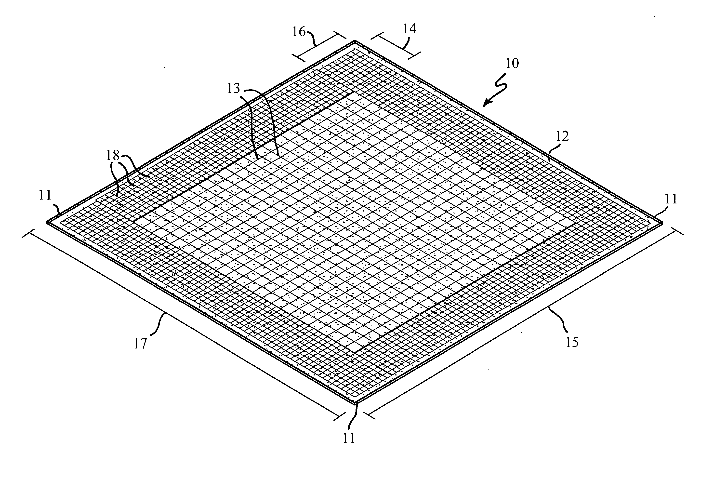
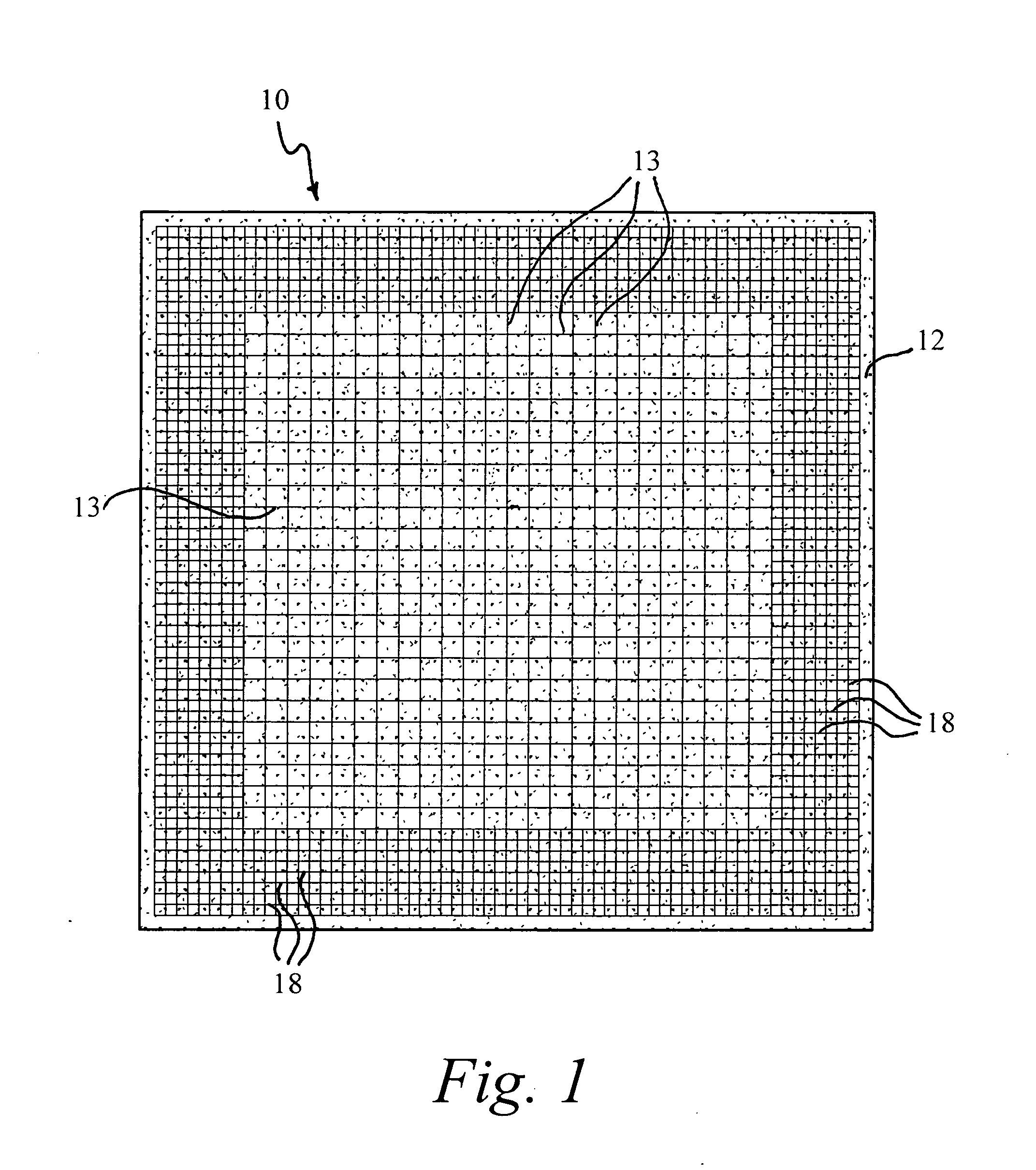
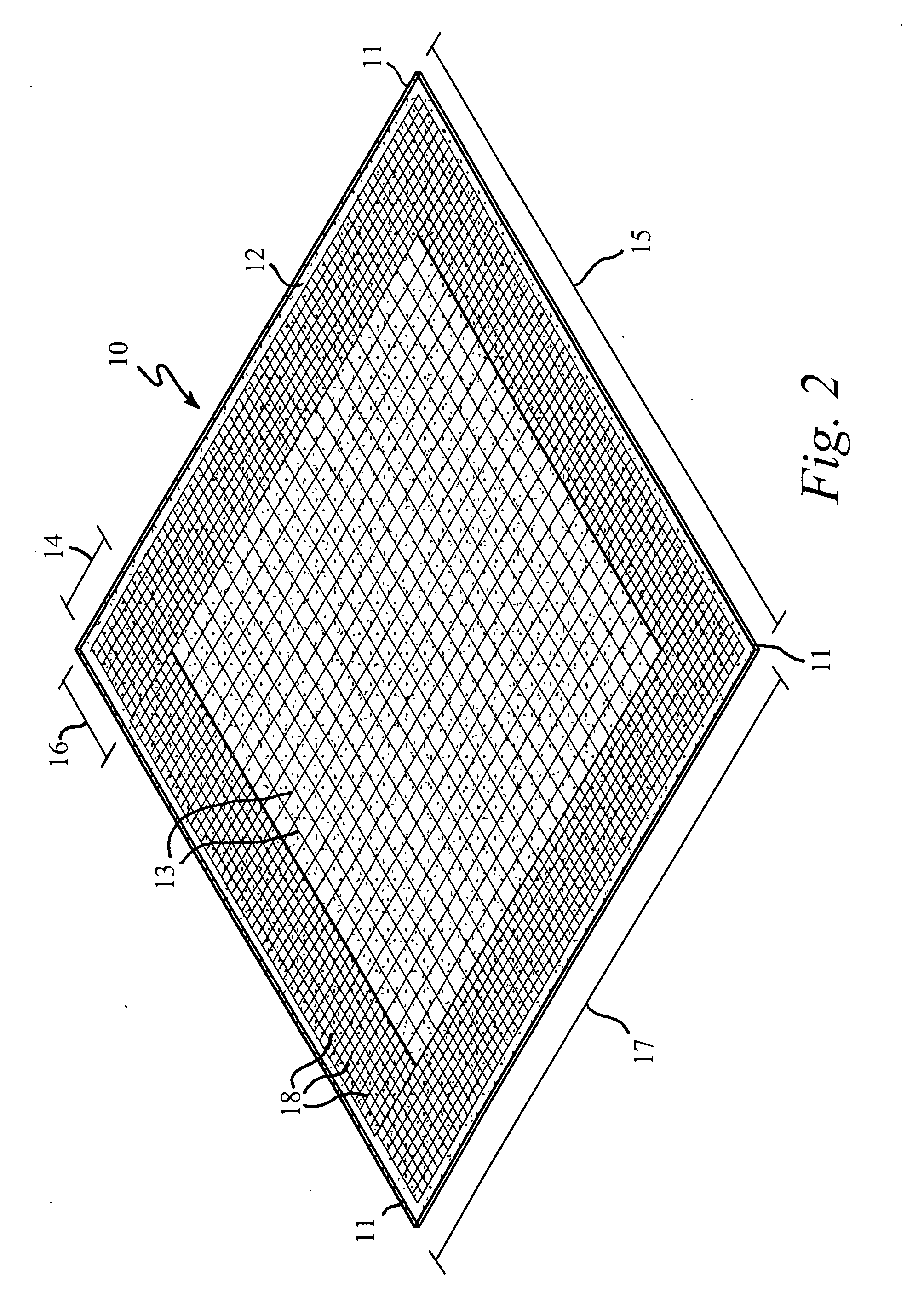
[0025]The following example, which is provided by way of illustration and without limitation, illustrates a slab 10 construction with a square pour area having a bulkhead length of 30 m, and a bulkhead width of 30 m. Pouring of the shrinkage compensating concrete slab 10, results in a construction having a major outer 12 and inner faces. With this example, the faces define a slab thickness of 20.32 cm. The centroid portion is 22.68 m and is surrounded by the peripheral portion. The centroid portion is defined by the perpendicular and longitudinal aligned array of the first plurality of reinforcing bars 13. The reinforcing bars 13 are an Imperial sized #4, being 1.27 cm in diameter. The reinforcing bars 13, 18 are deformed and are non-prestressed and non-post stressed steel. The bars are embedded on a plane which lies 13.41 cm from the inner face of the slab, and downwardly from the outer face 12 to approximately ⅓ of the slab thickness (6.71 cm). In this manner, the first plurality ...


PUM


Abstract

A reinforced shrinkage compensating concrete slab has a major outer and inner faces defining a slab thickness and a centroid portion surrounded by a peripheral portion having outer peripheral edges defining a bulkhead length and width. A first plurality of reinforcing bars is embedded within the concrete slab on a plane which is substantially parallel to the major outer and inner faces. The first reinforcing bars extend in a first array having a first dimension defining a first on-centers-each-way orientation. A second plurality of reinforcing bars is embedded within the peripheral portion of the concrete slab in a second array which is a substantially intersecting and coplanar construction in relation to the first reinforcing bars. The second plurality of reinforcing bars are restricted to the peripheral portion and aligned with the expansive and shrinkage forces on a second dimension defining a second on-centers-each-way orientation so that the expansive and shrinkage forces are restrained.

Description

CROSS REFERENCE TO RELATED APPLICATIONS[0001]None.STATEMENT OF FEDERALLY SPONSORED RESEARCH[0002]None.BACKGROUND OF THE INVENTION[0003]1. Technical Field[0004]The present invention relates to shrinkage compensating concrete slab structures. In particular, it relates to a reinforced shrinkage compensating concrete slab structure having first and second reinforcing bar arrays which define a centroid and peripheral portions so that active expansive and shrinkage forces are restrained.[0005]2. Background Art[0006]The construction of shrinkage compensating concrete slab structures is generally known. Such constructions are sometimes referred to as “self-stressing concrete” and to “chemically prestressed concrete.” Unlike traditional Portland cement based concrete, the shrinkage compensating concrete has a constituent that actively causes the concrete to volumetrically enlarge. According to the American Concrete Institute (“ACI”), shrinkage compensating concrete means “a concrete that, wh...

Claims


Application Information

Patent Timeline
IPC IPC(8): E04B1/04
CPCE04C5/04E04C2/06
Inventor YTTERBERG, DONALD G.W.
Owner YTTERBERG DONALD G W
Why Eureka
Try Eureka