Veress needle with removable optical inserts

Inactive Publication Date: 2011-12-22
TYCO HEALTHCARE GRP LP
View PDF6 Cites 15 Cited by
  • Summary
  • Abstract
  • Description
  • Claims
  • Application Information

AI Technical Summary

Benefits of technology

[0008]Accordingly, the present disclosure is directed to a veress needle that includes a housing, a first optical insert, and a second optical insert. The housing includes one or more insufflation conduits and an elongate member. The housing may include one or more seals adapted to permit the sealed reception of one or both of the first and second optical inserts. The one or more insufflation conduits are adapted to permit the passage and reception of one or more fluids therethrough. The elongate member extends from the housing and is adapted for insertion within tissue to access an underlying tissue site. The housing defines a passage therethrough. The first and second optical inserts are operably associated with the housing and removably positionable within the passage of the housing while the elongate member remains positioned within tissue.
[0009]Each optical insert includes an optical assembly having one or more lenses and an ocular. The optical assembly includes a fiber optic image bundle. The optical assembly defines a chamber between the fiber optic image bundle and the one or more lenses. The chamber may include index matching material. The one or more lenses may be a standard lens. The one or more lenses may be diffractive lenses. The one or more lenses are adapted to receive an image and transmit the image to the ocular so that the image is perceptible through the ocular. The one or more lenses of the first optical insert transmit images that are in direct contact with the distal end of the first optical insert to the ocular of the first optical insert for contact viewing. The one or more lenses of the second optical insert transmit images that are disposed at a distance from the distal end the

Problems solved by technology

Moreover, laparoscopic and endoscopic procedures often require the surgeon to visually inspect and magnify organs, tissue

Method used


Image

  • Veress needle with removable optical inserts
  • Veress needle with removable optical inserts
  • Veress needle with removable optical inserts

Examples


Embodiment Construction

[0020]Detailed embodiments of the present disclosure are disclosed herein; however, the disclosed embodiments are merely exemplary of the disclosure, which may be embodied in various forms. Therefore, specific structural and functional details disclosed herein are not to be interpreted as limiting, but merely as a basis for the claims and as a representative basis for teaching one skilled in the art to variously employ the present disclosure in virtually any appropriately detailed structure.

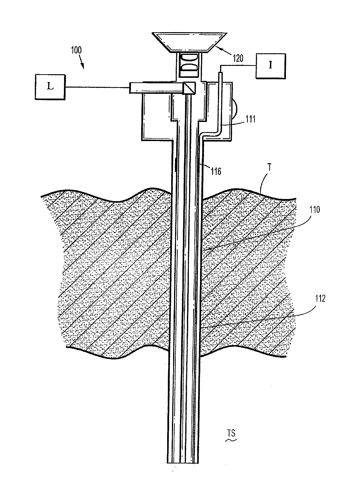
[0021]Particular embodiments of the present disclosure will be described herein with reference to the accompanying drawings. As shown in the drawings and as described throughout the following description, and as is traditional when referring to relative positioning on an object, the term “proximal” refers to the end of the apparatus that is closer to the user and the term “distal” refers to the end of the apparatus that is farther from the user. In the following description, well-known functions ...


PUM


Abstract

A veress needle including a housing, a first optical insert for contact viewing, and a second optical insert for distance viewing. The housing including one or more insufflation conduits and an elongate member. The one or more insufflation conduits being adapted to permit the passage and reception of at least one fluid therethrough. The housing defines a passage therethrough. The first and second optical inserts are operably associated with the housing and removably positionable within the passage of the housing while the elongate member remains positioned within tissue. Each optical insert includes an optical assembly having one or more lenses and an ocular. The one or more lenses are adapted to receive an image and transmit the image to the ocular so that the image is perceptible through the ocular.

Description

CROSS REFERENCE TO RELATED APPLICATION[0001]The present application claims the benefit of and priority to U.S. Provisional Application Ser. No. 61 / 356,149 filed on Jun. 18, 2010, the entire contents of which are incorporated herein by reference.BACKGROUND[0002]1. Technical Field[0003]This application generally relates to the field of laparoscopic surgery. More particularly, the present disclosure relates to veress needles for laparoscopic visualization of a body cavity.[0004]2. Description of Related Art[0005]In laparoscopic procedures, surgery is performed in the interior of the abdomen through a small incision. In endoscopic procedures, surgery is performed in any hollow viscus of the body through a narrow tube or cannula inserted through a small entrance incision in the skin. Since surgical procedures in the abdominal cavity of the body require insufflating gases to raise the cavity wall away from vital organs, the procedure is usually initiated by use of a veress needle through ...

Claims


Application Information

Patent Timeline
IPC IPC(8): A61B1/06A61B1/32
CPCA61B1/00105A61B1/00195A61B1/015A61B2019/5217A61B17/3474A61B2019/521A61B1/3132A61B2090/3614A61B2090/309
Inventor STANLEY, ERICDAVIS, MICHAEL R.LEINER, DENNISBETTUCHI, MICHAELHEINRICH, RUSSELL
Owner TYCO HEALTHCARE GRP LP
Why Eureka
Try Eureka