Bone implant interface system and method

a bone implant and interface technology, applied in the field of implants, can solve the problems of insufficient bone implant interface, direct impact on the long-term success of the implant procedure, and easy drawbacks of the procedur

Inactive Publication Date: 2011-12-22
4-WEB
View PDF13 Cites 153 Cited by
  • Summary
  • Abstract
  • Description
  • Claims
  • Application Information

AI Technical Summary

Problems solved by technology

Although orthopedic implants and procedures are common and have improved over the years, procedures may be susceptible to drawbacks, such as in insufficient interface between the bone and the implant.
The bone-implant interface may significantly impact how an implant integrates into the patient's anatomy and, thus, may directly impact long term success of an implant procedure.
Unfortunately, these fixation techniques often exhibit deficiencies, including varied and inadequate stress distribution at the bone-implant interface.
Inadequate stress distribution at the bone / implant interface may ultimately lead to a reduction in bone density and thereby cause loosening of the implant In some instances, implants include a porous coating to promote adhesion to the bone Due to multidirectional forces being applied to implants at any given point in time, these coatings may not offer sufficient initial fixation.
This lack of fixation may enable micromotion which may lead to irregular bone healing and remodeling, lack of adherence and non-uniformity.
Additionally porous coatings may not provide sufficient thickness to facilitate effective bone tissue in-growth within the dynamic environment that implants exist.
Such inadequate structural designs often lead to inadequate long term fixation due to issues such as implant component loosening, implant instability, migration of the implant, rotation of the implant, premature wear on articulating surfaces of the bone or implant, periprosthetic fractures of bone at or near the bone-implant interface, as well as other issues.

Method used


Image

  • Bone implant interface system and method
  • Bone implant interface system and method
  • Bone implant interface system and method

Examples


Embodiment Construction

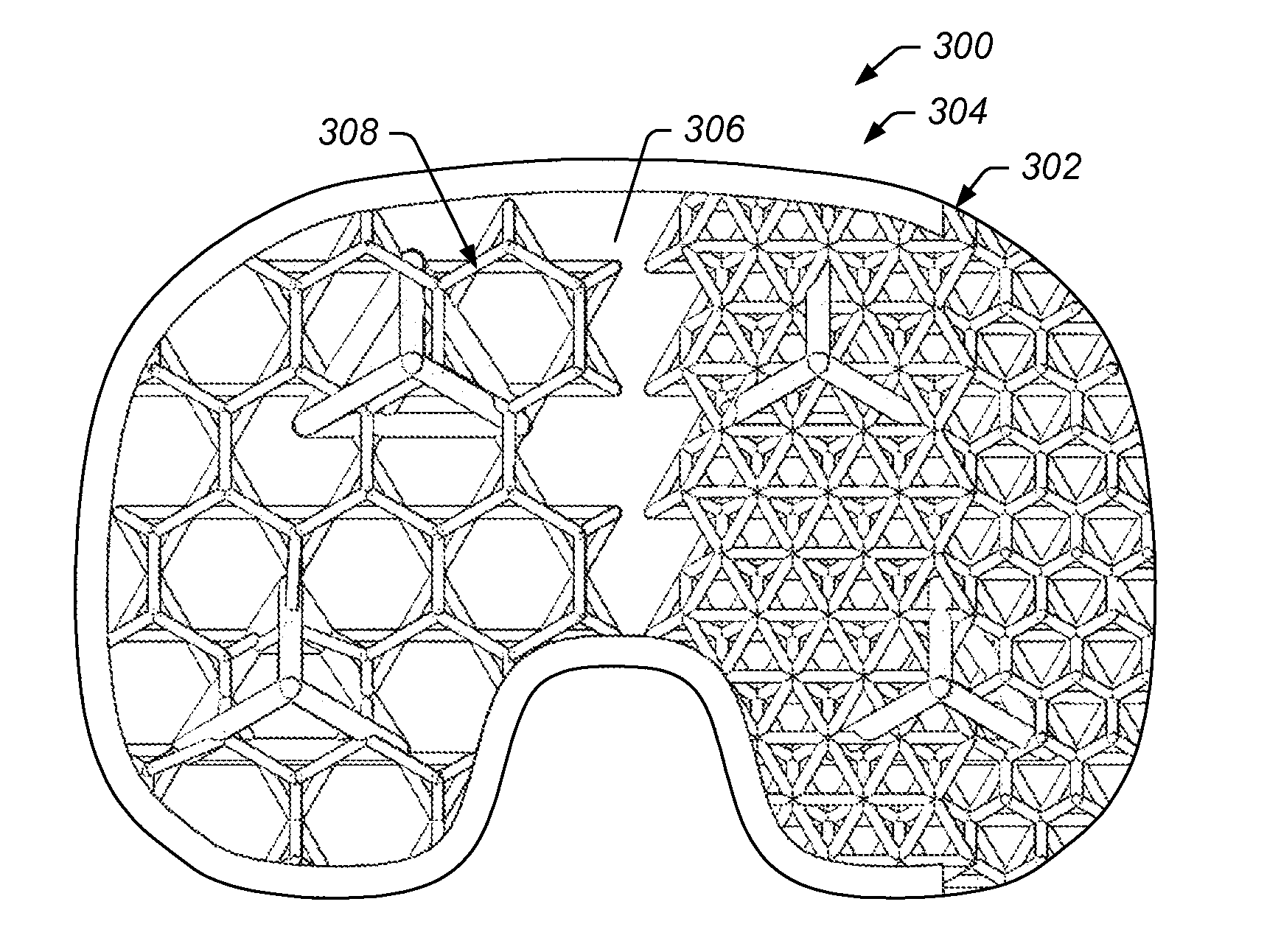
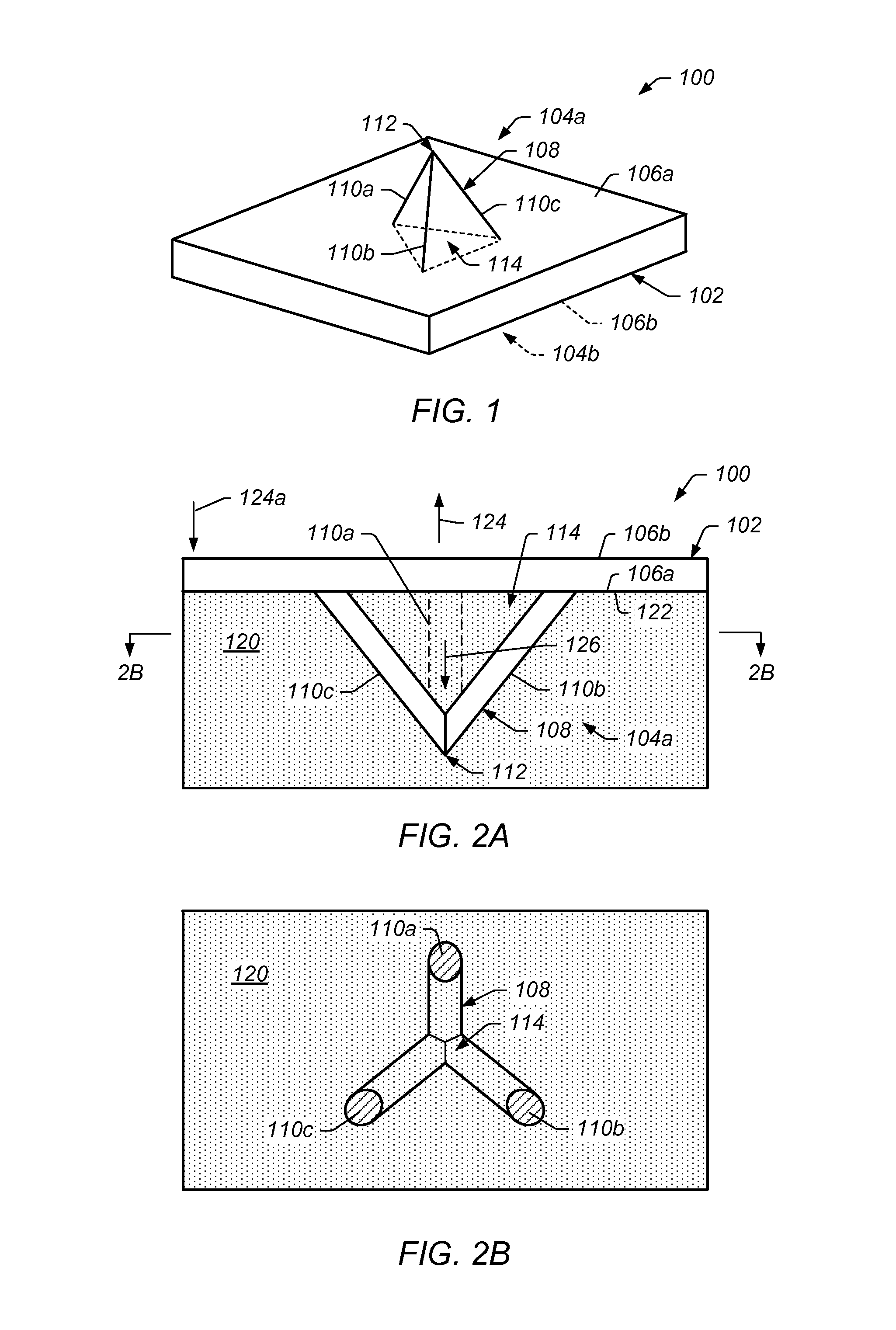
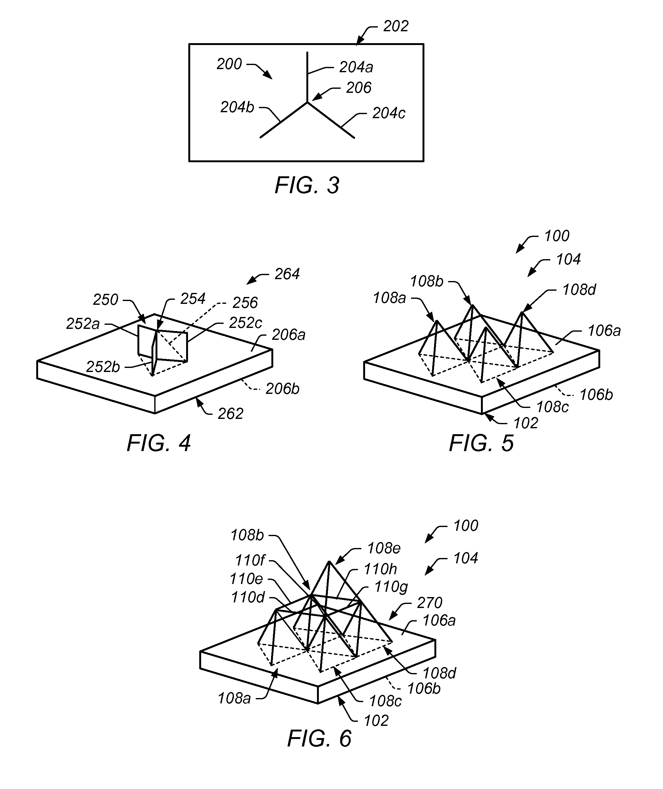
[0028]As discussed in more detail below, certain embodiments of the present technique include a system and method for implants, including orthopedic implants. In some embodiments, an implant includes a bone-implant interface that facilitates integration of the implant with adjacent bone structures. In certain embodiments, the bone-implant interface provides for effective load transfer between the implant and the adjacent bone. In some embodiments, a bone-implant interface includes a surface of the implant having an interface structure (e.g., a rod structure) extending therefrom that is to be disposed in bone structure during use. In certain embodiments, the rod structure includes a first portion extending away from the surface of the implant and a second portion oriented at least partially oblique to the first portion of the rod structure. In certain embodiments, the rod structure comprises a two dimensional structure extending from the surface. In some embodiments, the rod structur...


PUM


Abstract

An orthopedic implant that includes an implant body having a bone contact surface to be in contact or near contact with a bone structure during use, wherein the bone contact surface has a bone interface structure protruding therefrom. The bone interface structure includes a first elongated portion to be at least partially pressed into the bone structure during use, and a second elongated portion to be at least partially pressed into the bone structure during use. The second elongated portion is coupled to the first elongated portion and extends from the first elongated portion at an angle oblique to the first elongated portion.

Description

BACKGROUND[0001]1. Field of the Invention[0002]The present invention relates generally to medical devices and, more particularly to implants.[0003]2. Description of Related Art[0004]Implants may be used in human and / or animals to support and / or secure one or more bones. Orthopedic implants are designed to be placed in the body as a replacement for damaged joints or repair of broken bones. For example, a knee replacement procedure may include replacing diseased or damaged joint surfaces of the knee with implants, such as metal and plastic components shaped to allow continued motion of the knee. Although orthopedic implants and procedures are common and have improved over the years, procedures may be susceptible to drawbacks, such as in insufficient interface between the bone and the implant. The bone-implant interface may significantly impact how an implant integrates into the patient's anatomy and, thus, may directly impact long term success of an implant procedure. Providing a suff...

Claims


Application Information

Patent Timeline
Patent Type & Authority Applications(United States)
IPC IPC(8): A61F2/30
CPCA61F2/30767A61F2002/4475A61F2/30907A61F2/38A61F2/40A61F2002/30131A61F2002/30176A61F2002/30273A61F2002/30823A61F2002/30838A61F2002/30841A61F2002/30843A61F2002/30883A61F2/46A61F2/447A61F2/30771A61F2002/30593
Inventor HUNT, JESSEE
Owner 4-WEB
Why Eureka
Try Eureka