
Squeegee assembly

a vacuuming and squeegee technology, applied in the field of vacuuming squeegees, can solve the problems of dirty liquid pooling against a portion of the rear, creating safety hazards for individuals, and different types of floor surfaces, so as to improve the airflow into the suction tube, improve the pickup effect, and minimize or prevent the pooling of liquid.

Active Publication Date: 2011-12-29
NILFISK
View PDF9 Cites 2 Cited by
  • Summary
  • Abstract
  • Description
  • Claims
  • Application Information

AI Technical Summary

Benefits of technology

[0011]Thus, the present invention provides a novel squeegee assembly with improved pickup on rough surfaces, grouted tile or textured surfaces, pitted surfaces, or over seams and cracks in a surface.
[0012]The present invention also provides a novel squeegee assembly having improved airflow into the suction tube.
[0013]Further, the present invention provides a novel squeegee assembly having airflow through the rear blade to minimize or prevent pooling of liquid within the squeegee assembly.

Problems solved by technology

However, floor surfaces are of a variety of types which are not always level and / or completely smooth such as by design as in the case of grouted tile or textured floors, by necessity or damage such as in the case of seams and / or cracks, or by wear such as rough or pitted surfaces.
However, in some conventional squeegee assemblies, dirty liquid may pool against a portion of the rear flexible blade adjacent the suction tube due to the flow dynamics within the suction chamber formed between the front and rear flexible blades.
Such puddles are not only aesthetically displeasing, but they also create safety hazards for individuals who must walk across the floor after the floor has been cleaned.
However, this solution has proved costly and is not ideal due to the increased power demands.
Moreover, increasing the strength of the vacuum pump does not eliminate the area of low air flow near the vacuum port.
However, this solution has not been successful because reducing the space between the front and rear flexible blades limits the width of the suction port, which in turn necessitates an extreme transition from a narrow slotted vacuum port to a round vacuum hose.
Such an severe transition adds height to the squeegee assembly and may become easily clogged with debris.
As a result, it is almost impossible to suction all of the dirty liquid from grout lines and cracks effectively with a conventional vacuumized squeegee.

Method used


Image

  • Squeegee assembly
  • Squeegee assembly
  • Squeegee assembly

Examples


Embodiment Construction

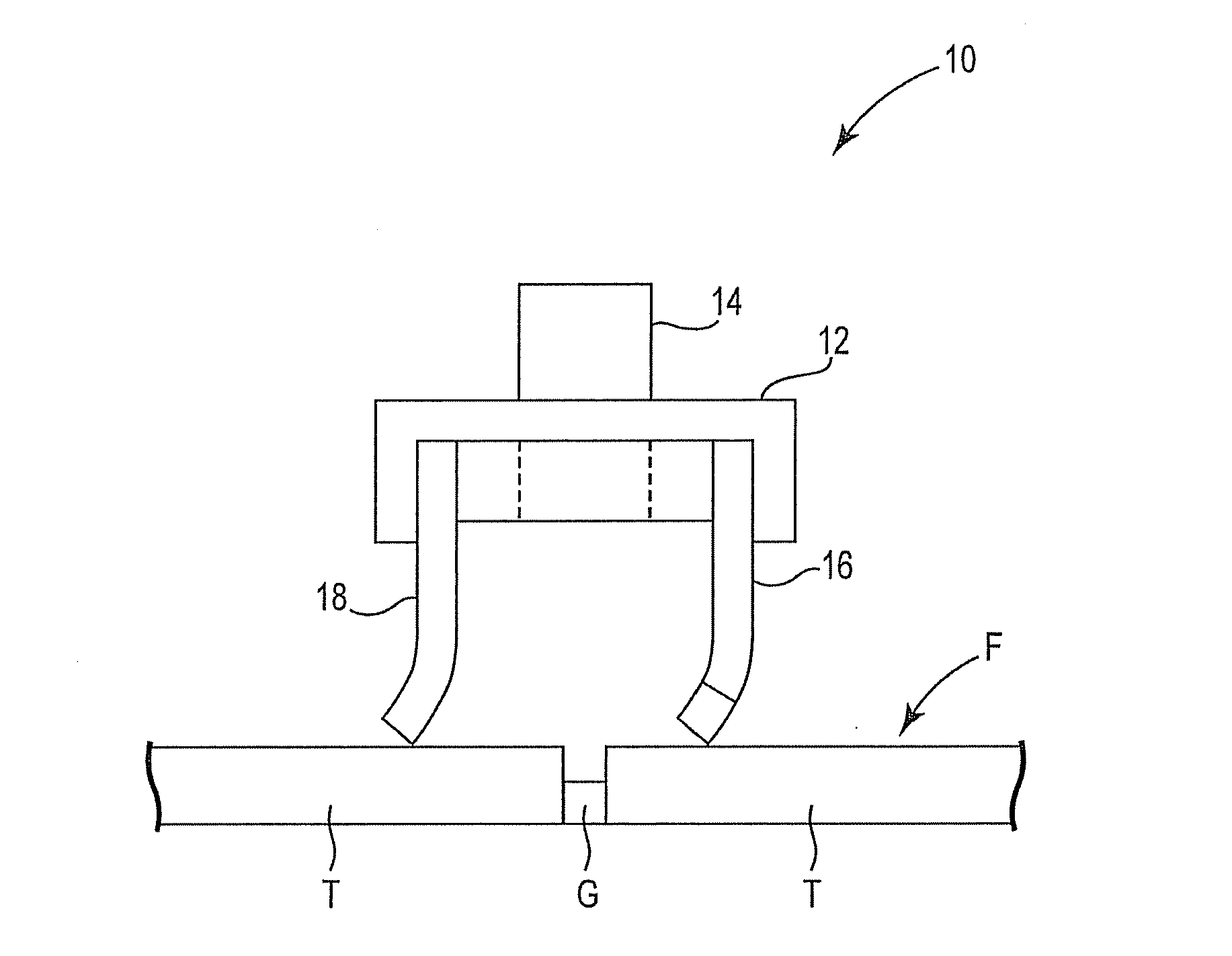
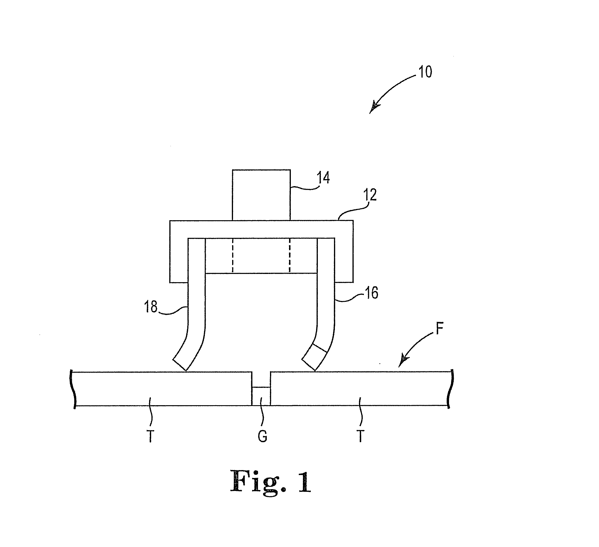
[0029]Generally speaking, the present invention involves an improved squeegee assembly for wiping a surface and collecting a liquid through vacuum pickup. FIG. 3 is a perspective view of one such exemplary squeegee assembly 20 in accordance with the present invention. As illustrated in FIG. 3, squeegee assembly 20 generally includes front flexible blade 22, rear flexible blade 24, support 26, and suction tube 28 structured for connection to a vacuum source. Front and rear flexible blades 22 and 24 extend from a bottom side of support 26, and are structured and designed to contact a floor surface. An upper end 30 of suction tube 28 extends from a top side 32 of support 26. Also extending from top side 32 of support 26 are connection means 34 for connecting squeegee assembly 20 to a surface cleaning machine. Any suitable connection means may be used without departing from the intended scope of the present invention.

[0030]As will be appreciated by those skilled in the art, squeegee ass...


PUM


Abstract

A squeegee assembly for wiping a surface comprises a front flexible blade having an outer surface, an inner surface and a floor engaging edge, a rear flexible blade having an outer surface, an inner surface and a wiping edge, a support upon which the front and rear flexible blades are mounted, a vacuumized chamber bounded by the front blade, rear blade, support, and the surface, and a suction tube coupled to the support and positioned between the front and rear flexible blades. The rear flexible blade includes at least one aperture extending between the outer surface and the inner surface and spaced from the wiping edge.

Description

BACKGROUND OF THE INVENTION[0001]The present invention relates generally to a cleaning apparatus. More specifically, the present invention relates to a vacuumized squeegee assembly structured for attachment to a floor cleaning system and having improved pickup capabilities.[0002]The use of vacuumized squeegee assemblies for wiping a surface and collecting dirty solution is conventional in many applications including, but not limited to, floor surface cleaning machines such as floor scrubbers. Typically, the front and rear blades of the squeegee assembly are always in contact with the floor surface so that any liquid on the floor surface is exposed to, picked up, and carried by airflow in the squeegee assembly. The rear blade in particular is provided with sufficient downward force to bend the blade outward so that only one edge of the blade engages the floor surface. Exemplary squeegee assemblies incorporating front and rear blades are disclosed in U.S. Pat. Nos. 7,254,867 and 6,557...

Claims


Application Information

Patent Timeline
Patent Type & Authority Applications(United States)
IPC IPC(8): A47L5/00
CPCA47L11/4044A47L11/30
Inventor WOOD, DAVID W.
Owner NILFISK
Features
  • Generate Ideas
  • Intellectual Property
  • Life Sciences
  • Materials
  • Tech Scout
  • Unparalleled Data Quality
  • Higher Quality Content
  • 60% Fewer Hallucinations
Learn More