
System for cementing tubulars comprising a mud motor

a cementing tubular and motor technology, applied in the field of cementing tubulars, can solve the problems of undesirable ports between the interior and exterior of the casing, insufficient hole drilling through the wall, and adversely affecting the pumping rate, and achieve the effect of high pumping ra

Inactive Publication Date: 2011-12-29
TRICAN WELL SERVICE
View PDF3 Cites 12 Cited by
  • Summary
  • Abstract
  • Description
  • Claims
  • Application Information

AI Technical Summary

Benefits of technology

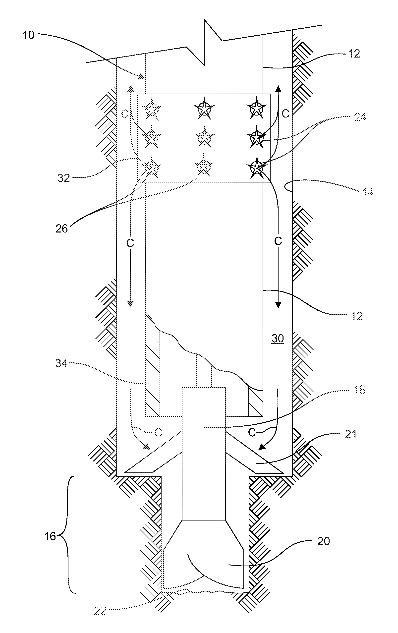
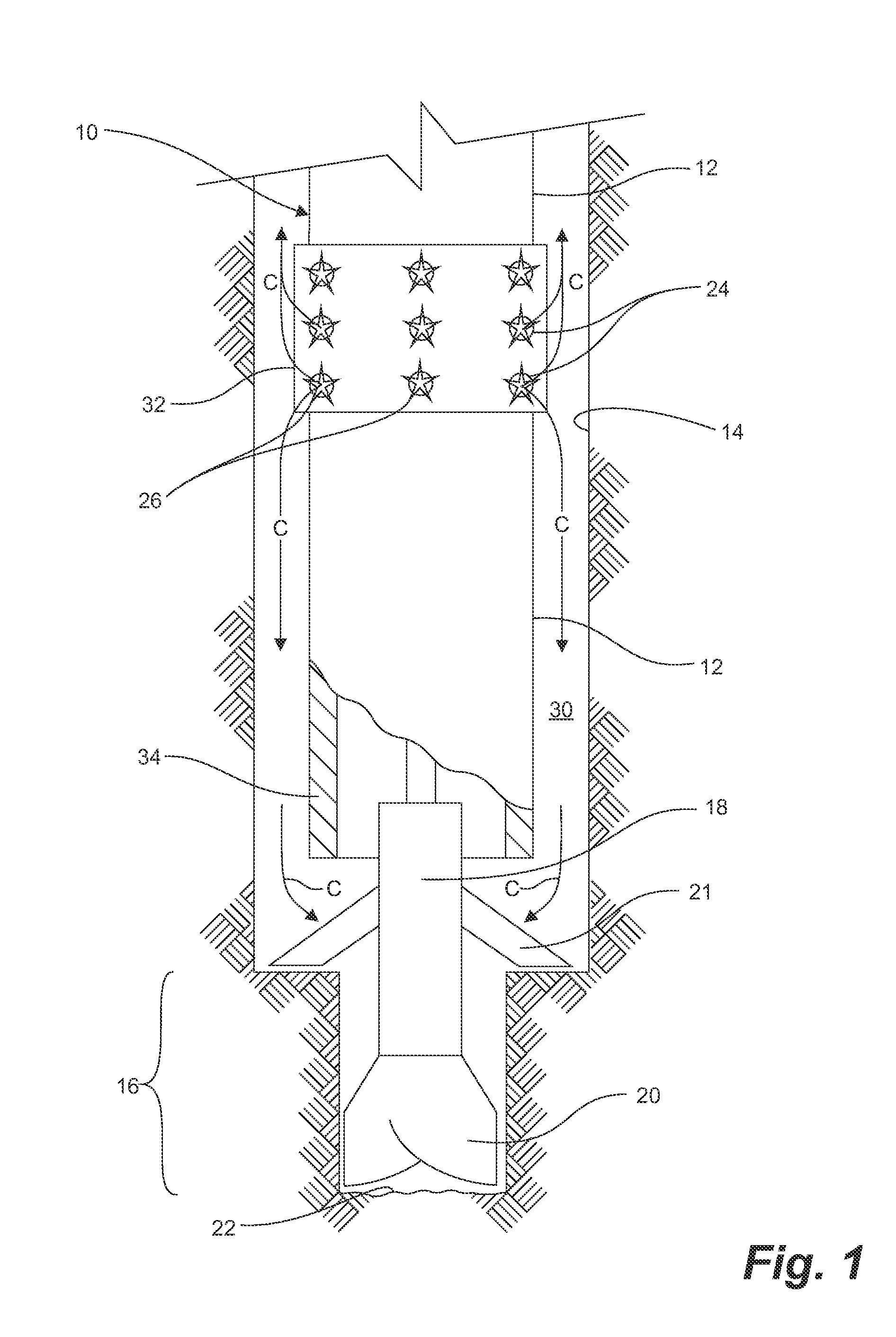
[0012]Embodiments of the invention utilize two or more burst disks located at or above a mud motor in a tubular string to permit cement to flow therethrough, once ruptured, and substantially bypass the mud motor.
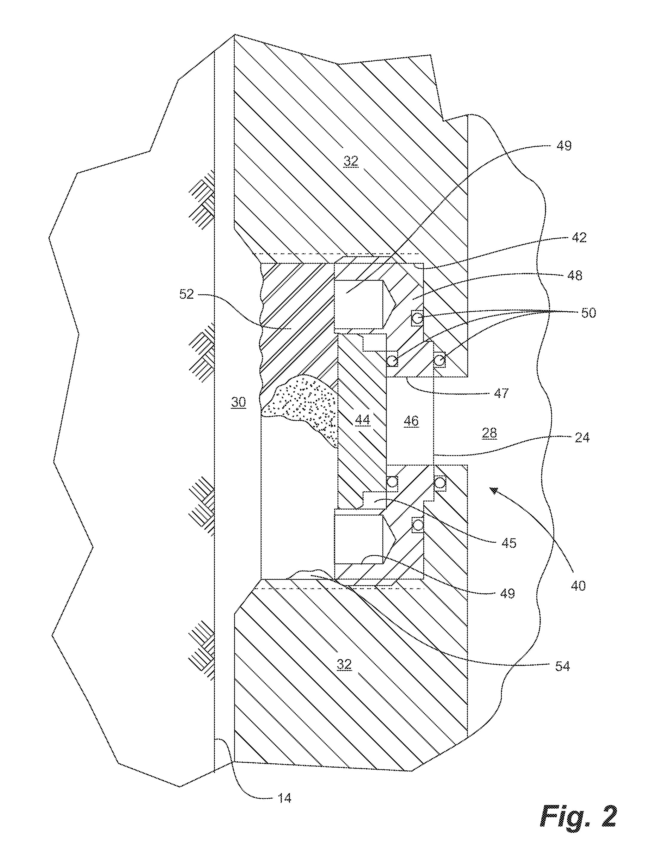
[0013]A cap is spaced above the burst disk for forming a chamber therebetween. The chamber remains at a substantially fixed and known pressure, such as about atmospheric pressure, when the tubular string is run into the wellbore. Thus, each of the two or more burst disks is unaffected by the variable hydrostatic pressure of fluids in the annulus. As all of the rupture disks will rupture at substantially the same threshold pressure, forming two or more open ports, pumping of cement is possible at a desired, relatively high pumping rate, which is greater than a pumping rate through a single, open port formed by a single ruptured burst disk, typical of the prior art.
[0014]In a broad aspect, a method for cementing a tubular conveyance string in a wellbore traversing a subterranean formation, comprises drilling the wellbore with a mud motor supported on the tubular conveyance string and forming an annulus therebetween. The tubular conveyance string has a bore and two or more burst disks fit to the string at or uphole of the mud motor. Each of the two or more burst disks has a cap spaced radially outward from the burst disk for forming a chamber therebetween. The chamber is maintained at a substantially fixed and known pressure, the two or more burst disks having a same threshold pressure at which the two or more burst disks rupture. The mud motor is abandoned downhole. Cement is pumped downhole in the bore of the conveyance string. The bore is pressurized to the threshold pressure for rupturing the two or more burst disks for forming two or more open ports therethrough. Thereafter, cement is continued to be pumped downhole in the bore of the conveyance string and through the two or more open ports to the annulus.
[0015]In another broad aspect, a system for completion of a wellbore traversing a subterranean formation comprises a mud motor having a drill bit and supported by a tubular conveyance string having a bore and forming an annulus with the wellbore. Two or more burst disks are fit to the string at or uphole of the mud motor, each of the two or more burst disks having a threshold pressure at which the burst disk ruptures. A cap is spaced radially outward from the burst disk for forming a chamber therebetween, the chamber being maintained at a substantially fixed and known pressure. When the drilling of the wellbore is stopped and cement is pumped downhole through the bore of the conveyance string, the pressure of the cement at the two or more burst disks reaches the threshold pressure for rupturing the two or more burst disks and forming two or more open ports therethrough for delivering the cement to the annulus.

Problems solved by technology

Further, mud motors have a high pressure differential across motor which may adversely affect the rate at which the cement is pumped and delivered to the annulus between the casing and the wellbore.
As will be appreciated by one of skill in the art, a hole drilled through the wall is insufficient.
There are many steps in the drilling process where having ports open between the interior and exterior of the casing would be undesirable.
Applicant has found however, that conventional burst disks do not open reliably.

Method used


Image

  • System for cementing tubulars comprising a mud motor
  • System for cementing tubulars comprising a mud motor
  • System for cementing tubulars comprising a mud motor

Examples


example

[0044]A wellbore having a total vertical depth (TVD) of 1200 m and a total measured depth (TMD) of 3000 m is drilled using 4.5 inch casing and a bottomhole assembly comprising a mud motor. A hydrostatic pressure of 11.7 MPa in the wellbore results in a calculated, maximum drilling pressure of about 30 MPa.

[0045]At or above the mud motor, a casing collar is positioned comprising fifteen burst disks according to an embodiment of the invention. Each of the burst disks has an orifice diameter of about 0.375 inches and a thickness of about 0.006 inches and is designed to have an absolute burst pressure of about 54.6 MPa for each of the burst disks.

[0046]In order to rupture substantially all of the burst disks, the pressure within the casing must be increased to a pressure threshold of about 43 MPa, measured at surface, in order to exceed the absolute pressure at which the disks will burst at depth in the wellbore. The burst threshold pressure, at surface, is about 13 MPa greater than the...


PUM


Abstract

A method and system for cementing a tubular and mud motor in a wellbore utilizing burst disks above the mud motor. The burst disks rupture to permit the cement to flow through the burst disks and bypass the mud motor. All of the burst disks reliably rupture at a predetermined and known threshold pressure so as to permit cement to be pumped at a desired rate through all of the ruptured burst disks. Each burst disk is provided with a cover for maintaining a chamber of a known pressure between the cap and the burst disk. All of the burst disks predictably and reliably rupture at the rated pressure.

Description

CROSS REFERENCE TO RELATED APPLICATIONS[0001]This application is a regular application claiming priority of U.S. Provisional Patent application Ser. No. 61 / 359,718, filed on Jun. 29, 2010, the entirety of which is incorporated herein by reference.FIELD OF THE INVENTION[0002]Embodiments of the invention are related to systems, apparatus and methods used during cementing of tubulars in a wellbore and, more particularly, to cementing tubulars which comprise a mud motor while minimizing the amount of cement passing through the mud motor.BACKGROUND OF THE INVENTION[0003]In oil and gas well drilling operations it is necessary to cement various tubular members to a subterranean formation at different points during the well drilling and completion operations. This practice is well known for various purposes, such as anchoring a surface casing to the earth to provide a solid leak-free top section of the well, and, in the lower portions of the well, to provide isolation between different subt...

Claims


Application Information

Patent Timeline
Patent Type & Authority Applications(United States)
IPC IPC(8): E21B33/14
CPCE21B34/063E21B33/14
Inventor SHERMAN, SCOTT
Owner TRICAN WELL SERVICE
Learn More