Assembly and method for placing a cement plug

Inactive Publication Date: 2011-07-07
SCHLUMBERGER TECH CORP
View PDF16 Cites 9 Cited by
  • Summary
  • Abstract
  • Description
  • Claims
  • Application Information

AI Technical Summary

Benefits of technology

[0010]The guide shoe may further comprise a differential pressure valve for reducing any piston effect on a geological formation surrounding the well-bore.
[0021]The invention enables enhancing the safety and the quality of the cement plug placement operation.
[0022]Further, the invention allows high pump rates throughout the operation, and avoids having to balance the plug.
[0023]Furthermore, the invention eliminates contamination caused by pulling the drill pipe through the plug after placement, and reduces the risk of cementing the drill pipe in the well-bore.

Problems solved by technology

In this condition, the preferred mud removal technique, namely turbulent flow is nearly impossible to achieve due to the important gap (annulus) existing between the stinger and the well-bore wall.
Further, there is also a risk that the cement sets with the drill pipe immersed in the well-bore.
Furthermore, after a cement plug has been placed, the drill pipe is pulled through the cement plug which may result in contamination.
Finally, the plug placement assembly must be completely pulled out of the well-bore before resuming any further operation to be conducted in the well-bore, which leads to a loss in rig time.

Method used


Image

  • Assembly and method for placing a cement plug
  • Assembly and method for placing a cement plug
  • Assembly and method for placing a cement plug

Examples


Embodiment Construction

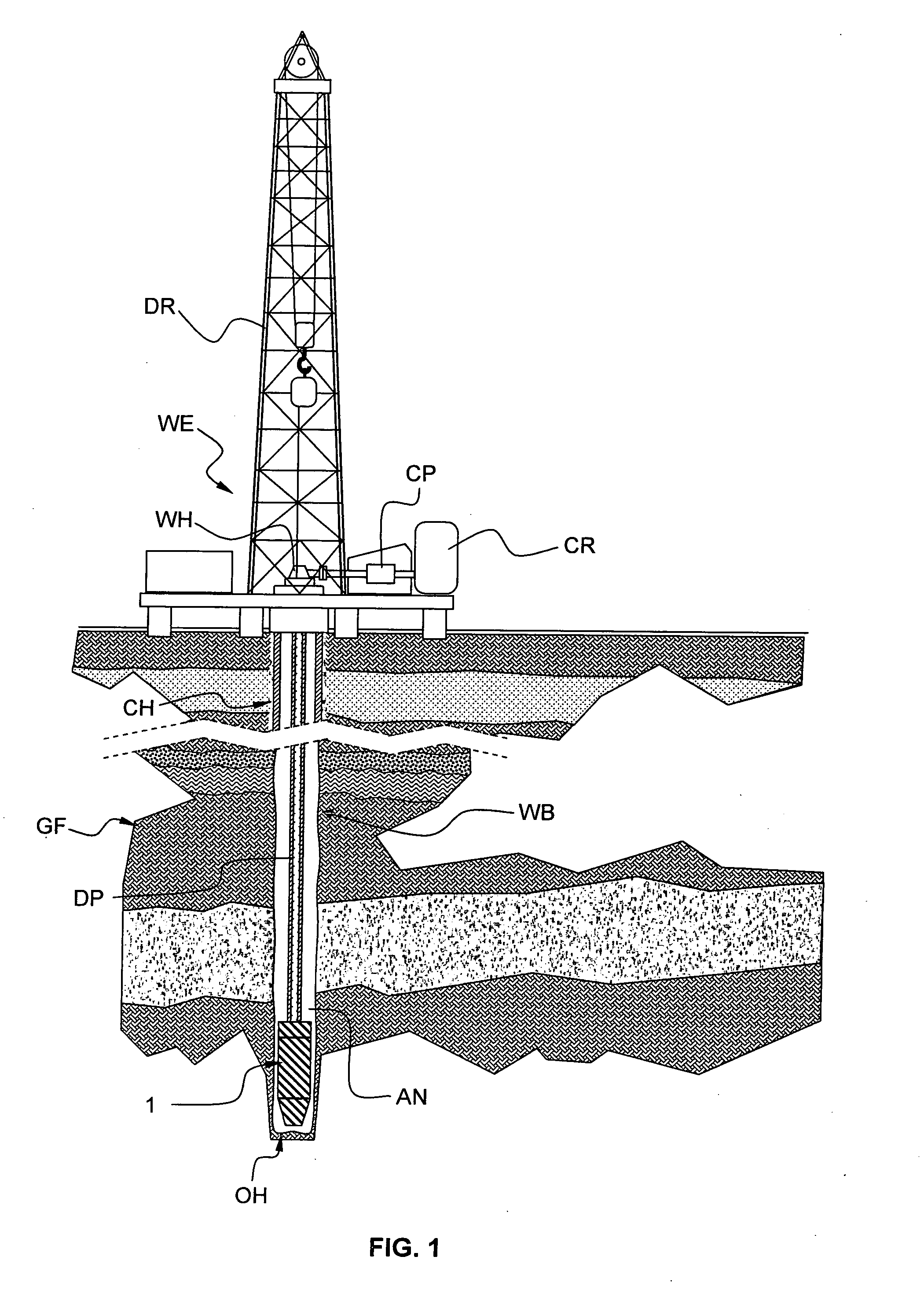
[0030]FIG. 1 schematically shows an onshore hydrocarbon well location and equipments WE above a hydrocarbon geological formation GF after drilling operation has been carried out and after a drill pipe DP has been run. At this stage, the well-bore WB is an open-hole OH generally filled with various fluid mixtures (e.g. the drilling mud or the like). The well-bore WB may also be partially cased CH. The equipment WE comprises a drilling rig DR for running the drill pipe DP in the well-bore, cementing equipment comprising cement silo CR and pumping arrangement CP, and a well head and stuffing box arrangement WH providing a sealing for deploying the drill pipe DP or pumping down the cement into the generally pressurized well-bore WB. Subsequently, cementing operations are generally undertaken to seal the annulus AN (i.e. the space between the well-bore WB and the casing where fluid can flow). A first application is primary cementing which purpose is to achieve hydraulic isolation around ...


PUM


Abstract

An assembly for placing a cement plug (1) in a well-bore comprises a landing and disconnecting collar (2), a shoe track (3), a circulation element (4), and a guide shoe (5), said elements forming an internal conduit (10), the circulation element (4) comprising side conduits (8) directed towards a well-bore wall (WBW). The assembly (1) diameter is such as to create a narrow annulus (AN2) in which a fluid pumped through the side conduits (8) circulates in the annulus according to a turbulent flow. The assembly (1) further comprises a sealing element (6) comprising a bottom sealing element (6A). The landing and disconnecting collar (2), shoe track (3), circulation element (4), and guide shoe (5) are made of material that are drillable, the elements forming the cement plug when a cement slurry (CS) is set into the annulus (AN2) and the internal conduit (10).

Description

FIELD OF THE INVENTION[0001]An aspect of the invention relates to an assembly for placing a cement plug in a well-bore. Another aspect of the invention also relates to a corresponding cement plug placing method.[0002]A particular application of the invention relates to the oilfield industry, for example in cementing operation.BACKGROUND OF THE INVENTION[0003]During a hydrocarbon well drilling operation and after a hydrocarbon well has been drilled, various fluid injecting operations are generally carried out. The fluid injecting operations serves various purposes, for example delivering a cement slurry for borehole cementing operation. These operations are well known in the oilfield industry.[0004]Typically, cement plug placement techniques recommend the use of a stinger for the section of the drill pipe immersed in the fluid in the borehole, the stinger having a diameter substantially smaller than the well-bore diameter. In this condition, the preferred mud removal technique, namel...

Claims


Application Information

Patent Timeline
IPC IPC(8): E21B33/00
CPCE21B33/14
Inventor MAUTH, KEVINCARRASQUILLA, JUAN
Owner SCHLUMBERGER TECH CORP
Why Eureka
Try Eureka