Zoom lens
a zoom lens and zoom technology, applied in the field of zoom lenses, can solve the problems that the fno cannot be effectively suppressed at the same time, and achieve the effects of less distortion, long back focus, and high telecentricity
- Summary
- Abstract
- Description
- Claims
- Application Information
AI Technical Summary
Benefits of technology
Problems solved by technology
Method used
Image
Examples
numerical example 1
[0082]
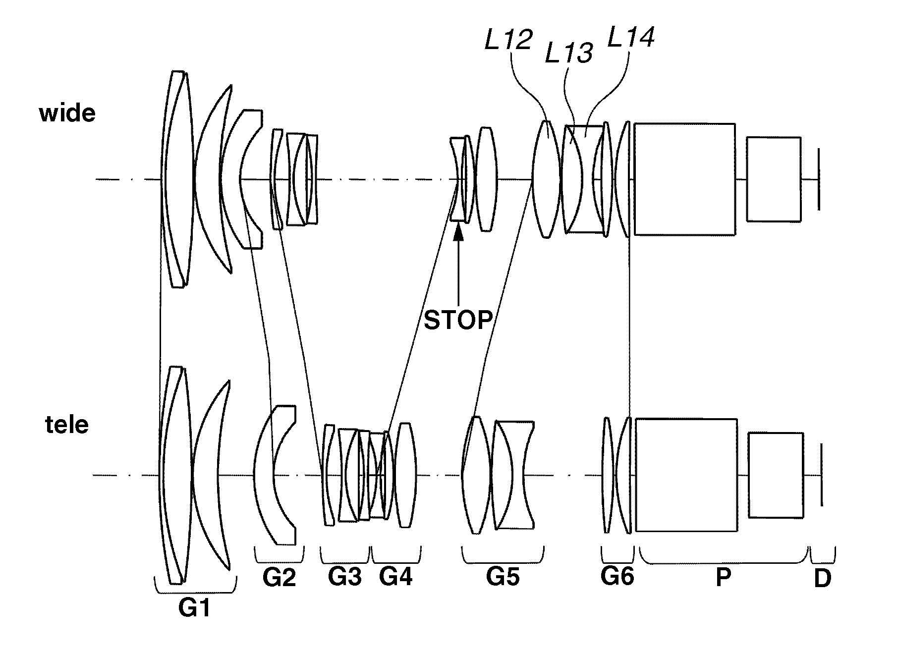
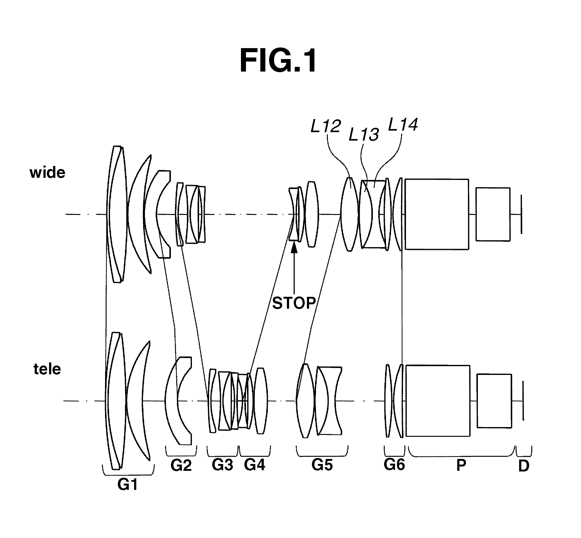
Unit: mmf = 55.5-112.2 Fno = 2.0-2.0 Zoom ratio: 2.0Surface DataSurfaceNo.rdnν1226.9291.701.8050025.42123.94912.041.5957060.53−353.5480.50459.37810.671.4970081.55145.000Variable648.9058.271.7735449.4731.481Variable8179.7761.701.4981464.1955.5796.5010−135.0001.701.4934666.31141.5315.531.8295834.812978.1742.2413−74.9061.701.5717142.314210.908Variable15−41.2461.701.7241637.11686.2061.8517−539.0733.651.7079554.518−67.9570.531998.3019.001.8050025.420−88.981Variable2169.10712.001.4970081.522−65.7440.5023150.7988.811.4970081.524−43.0384.621.7201632.32548.078Variable26246.5744.641.4870070.227−136.9131.322863.2345.751.7023255.029903.2922.5030∞43.001.5163364.131∞5.0032∞23.001.8051825.433∞7.24Wide-MiddleAngleFocalTelephotoEndLengthEndVarious DataZoom ratio: 2.0Half13.41818.40276.712AngleOf ViewDistance Between Lens UnitsFocal55.589.5112.2Lengthsd50.5012.5815.33d713.0315.6920.81d1460.7225.273.67d2015.2716.5919.67d253.5722.9733.60
numerical example 2
[0083]
Unit: mmf = 55.2-111.7 Fno = 2.0-2.0 Zoom ratio: 2.0Surface DataSurfaceNo.rdnν1585.421.901.74727.49281.4015.281.81839.653−514.410.50471.907.921.49781.555145.00Variable658.969.691.48770.20733.49Variable8405.121.901.50262.13952.984.9910−135.001.901.49167.861142.356.951.77349.6012−280.371.9613−68.751.901.52264.7314445.19Variable15−41.131.901.75337.211696.582.5017−484.524.141.74951.2018−71.200.5019118.517.031.80525.4020−82.2314.192163.8815.001.49781.5522−69.760.5023171.359.191.49781.5524−43.373.001.73032.032548.57Variable26132.496.721.48770.2027−108.286.442871.557.611.68855.8729263.692.5030∞43.001.51664.1431∞5.0032∞23.001.80525.4333∞6.50Wide-MiddleAngleFocalTelephotoEndLengthEndDistance Between Lens UnitsFocal55.289.0111.7Lengthsd50.5018.7423.03d714.2112.7817.88d1466.1427.273.84d252.9024.9639.00Various DataHalf13.48.46.7AngleOf View
numerical example 3
[0084]
Unit: mmf = 55.3-111.9 Fno = 2.0-2.0 Zoom ratio: 2.0Surface DataSurfaceNo.rdnν1127.981.801.80525.402101.0513.481.48770.203−372.910.50461.129.581.49781.555145.00Variable669.677.001.52353.65730.12Variable880.911.801.48770.20946.265.1010−135.001.801.48770.201136.186.001.83437.2012389.872.8813−68.091.801.69230.2114824.81Variable15−40.081.801.78733.2216102.241.7417−353.613.691.83035.2218−66.700.501999.406.491.80525.4020−78.62Variable2181.709.411.49781.5522−64.640.5023212.808.431.49781.5524−43.231.801.75329.822560.00Variable26208.414.911.69755.5027−174.532.902872.858.701.77349.6029332.172.5030∞43.001.51664.1431∞5.0032∞23.001.80525.4333∞7.08Wide-MiddleAngleFocalTelephotoEndLengthEndDistance Between Lens UnitsFocal55.389.2111.9Lengthsd55.0016.5819.86d78.9010.6214.10d1460.3925.273.33d2020.4617.5518.46d252.6527.4041.65Various DataHalf13.48.46.7AngleOf View
PUM
 Abstract
Description
Claims
Application Information
 - R&D
- Intellectual Property
- Life Sciences
- Materials
- Tech Scout
- Unparalleled Data Quality
- Higher Quality Content
- 60% Fewer Hallucinations
Browse by: Latest US Patents, China's latest patents, Technical Efficacy Thesaurus, Application Domain, Technology Topic, Popular Technical Reports.
© 2025 PatSnap. All rights reserved.Legal|Privacy policy|Modern Slavery Act Transparency Statement|Sitemap|About US| Contact US: help@patsnap.com


