
Seamless fracture in a production pipeline

Active Publication Date: 2012-01-05
DREAMWORKS ANIMATION LLC
View PDF6 Cites 18 Cited by
  • Summary
  • Abstract
  • Description
  • Claims
  • Application Information

AI Technical Summary

Problems solved by technology

While methods have been developed to generate fracture effects as described above, conventional methods often produce gaps between edges of adjacent fragments, leaving visible fracture lines in the reconstructed object.
While these techniques prevent the viewer from seeing the fracture lines, these methods are time consuming and may prevent animators from using all possible viewing angles in a scene.
Additionally, conventional animation methods produce reconstructed objects having non-uniform surface characteristics between edges of adjacent fragments, creating visible discontinuities between the fragments.
While this may reduce the surface discontinuities, it is an inefficient and time-consuming process.

Method used


Image

  • Seamless fracture in a production pipeline
  • Seamless fracture in a production pipeline
  • Seamless fracture in a production pipeline

Examples


Embodiment Construction

[0024]The following description is presented to enable a person of ordinary skill in the art to make and use the various embodiments. Descriptions of specific devices, techniques, and applications are provided only as examples. Various modifications to the examples described herein will be readily apparent to those of ordinary skill in the art, and the general principles defined herein may be applied to other examples and applications without departing from the spirit and scope of the various embodiments. Thus, the various embodiments are not intended to be limited to the examples described herein and shown, but are to be accorded the scope consistent with the claims.

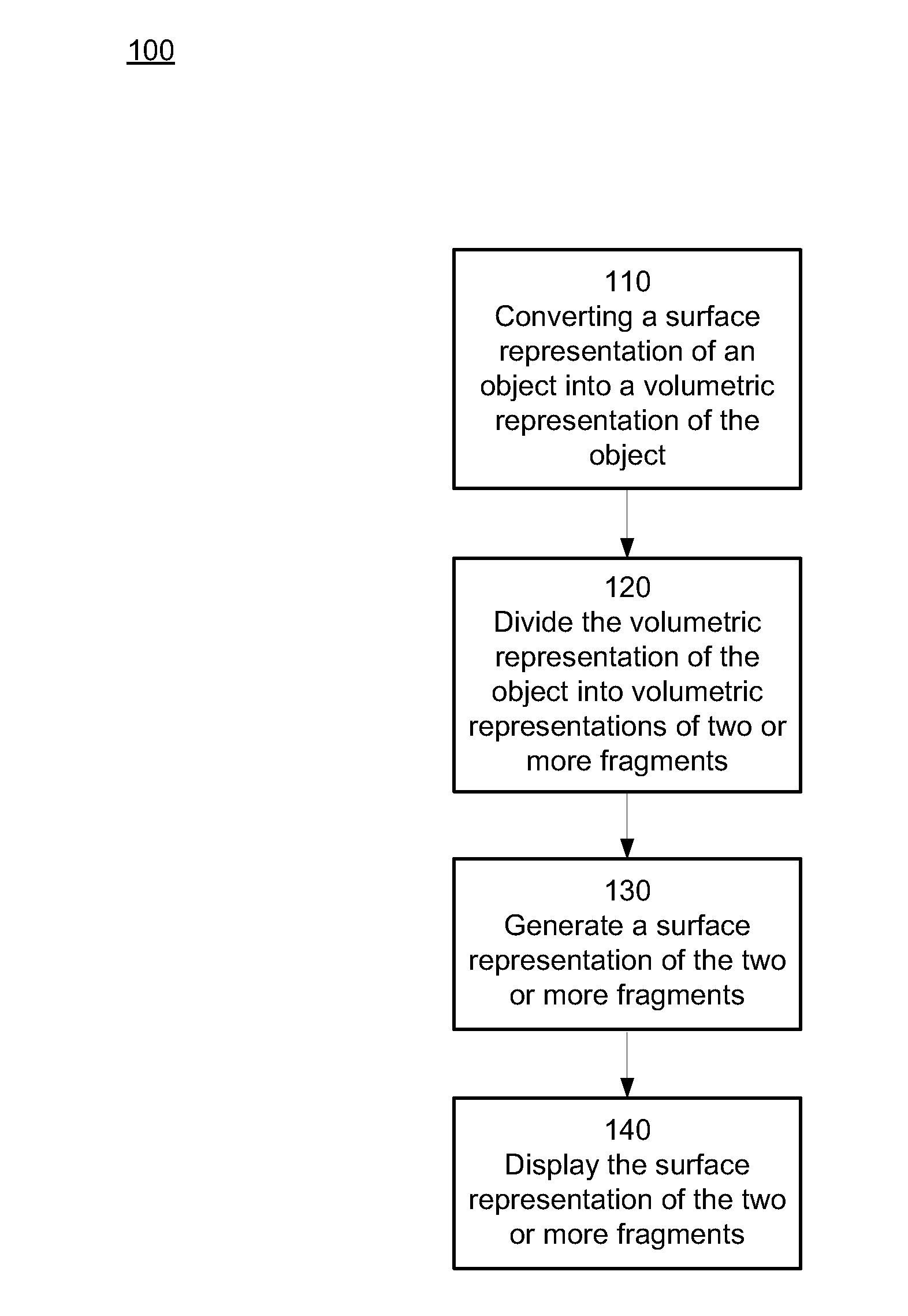
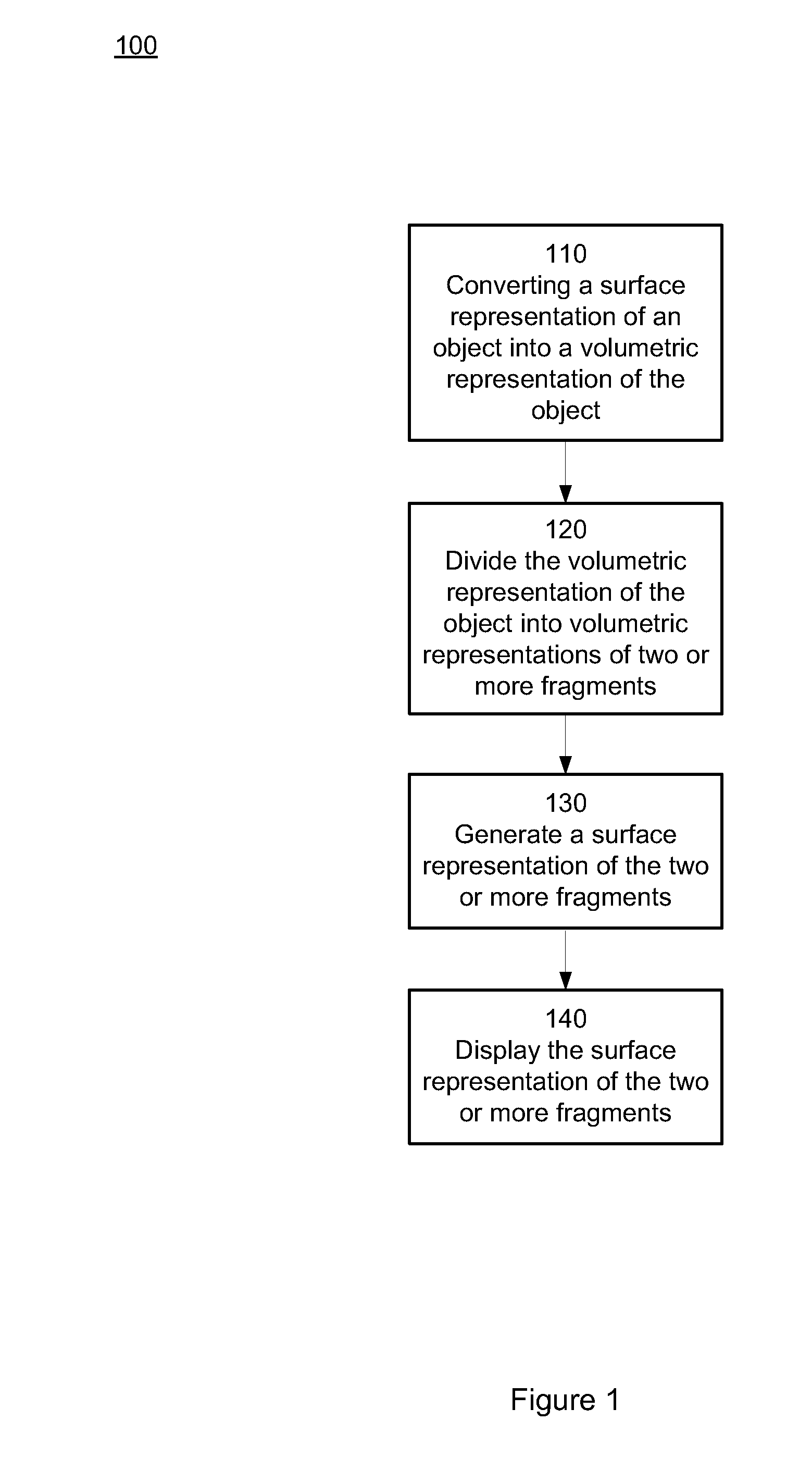
[0025]Various embodiments are described below relating to rendering an object to be fractured. In one example, an exemplary process for rendering an object to be fractured is provided. In one example process, a surface representation of an object may be converted into a volumetric representation of the object. The volum...


PUM


Abstract

Systems and processes for rendering fractures in an object are provided. In one example, a surface representation of an object may be converted into a volumetric representation of the object. The volumetric representation of the object may be divided into volumetric representations of two or more fragments. The volumetric representations of the two or more fragments may be converted into surface representations of the two or more fragments. Additional information associated with attributes of adjacent fragments may be used to convert the volumetric representations of the two or more fragments into surface representations of the two or more fragments. The surface representations of the two or more fragments may be displayed.

Description

BACKGROUND[0001]1. Field:[0002]This application relates generally to computer graphics, and more specifically to computer systems and processes for rendering fractures in objects.[0003]2. Related Art[0004]To show fracture effects in animated films, for example, to show a teacup breaking into multiple fragments, animators generally define the fragments prior to showing the breaking of the object. This may be done by taking a representation of the original object and dividing the representation into the multiple fragments. The fragments may then be assembled to reconstruct the object, creating the appearance that the reconstructed object is in an unfractured state. This reconstructed object may then be used to represent the object in its unfractured state throughout the animated film. Since the reconstructed object comprises multiple fragments, the multiple fragments may simply be separated from each other to animate fracturing of the object.[0005]While methods have been developed to ...

Claims


Application Information

Patent Timeline
IPC IPC(8): G06T17/20
CPCG06T17/20G06T13/60G06T13/20G06T2219/2012G06T19/20
Inventor GARG, AKASHMAXWELL, KYLELIPTON, DAVID
Owner DREAMWORKS ANIMATION LLC
Learn More