
Ophthalmic apparatus

a technology of ophthalmology and ophthalmology, which is applied in the field of ophthalmology, can solve the problems of insufficient resolution of conventional lcd to accurately display targets for high visual acuity

Inactive Publication Date: 2012-01-05
NIDEK CO LTD
View PDF1 Cites 35 Cited by
  • Summary
  • Abstract
  • Description
  • Claims
  • Application Information

AI Technical Summary

Benefits of technology

The invention is an ophthalmic apparatus that can observe the fundus of the eye. It includes a device that scans a laser beam to create a target on the fundus. The apparatus can change the size of the laser beam and the resolution of the target by adjusting the position of an optical member. This allows for more precise and accurate fundus observation.

Problems solved by technology

However, in a visual acuity test needing accurate display of smaller sized targets (targets for high visual acuity) as compared with the targets for visual field test, the resolution of the conventional LCD is insufficient to accurately display the targets for high visual acuity.

Method used


Image

  • Ophthalmic apparatus
  • Ophthalmic apparatus
  • Ophthalmic apparatus

Examples


Embodiment Construction

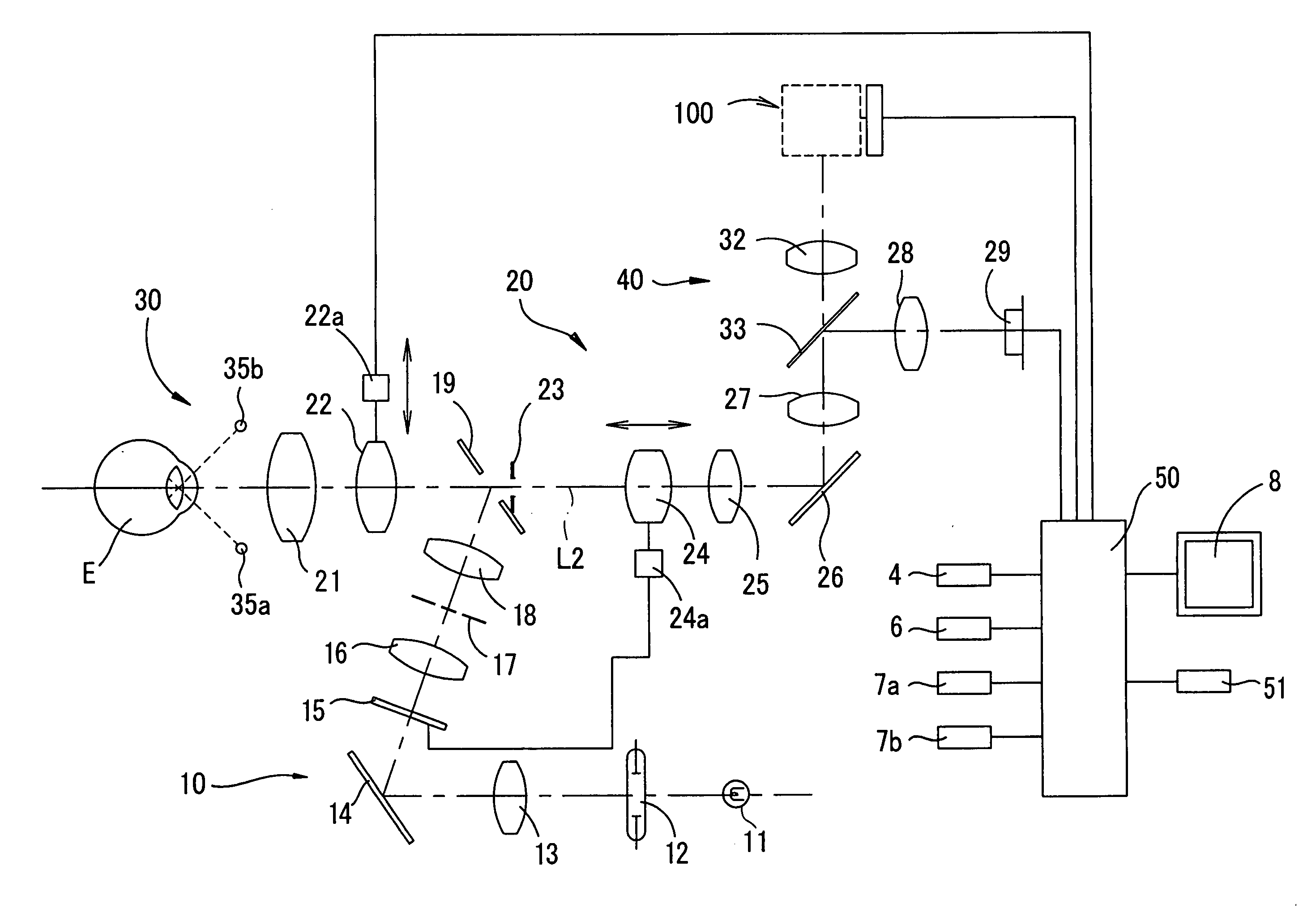
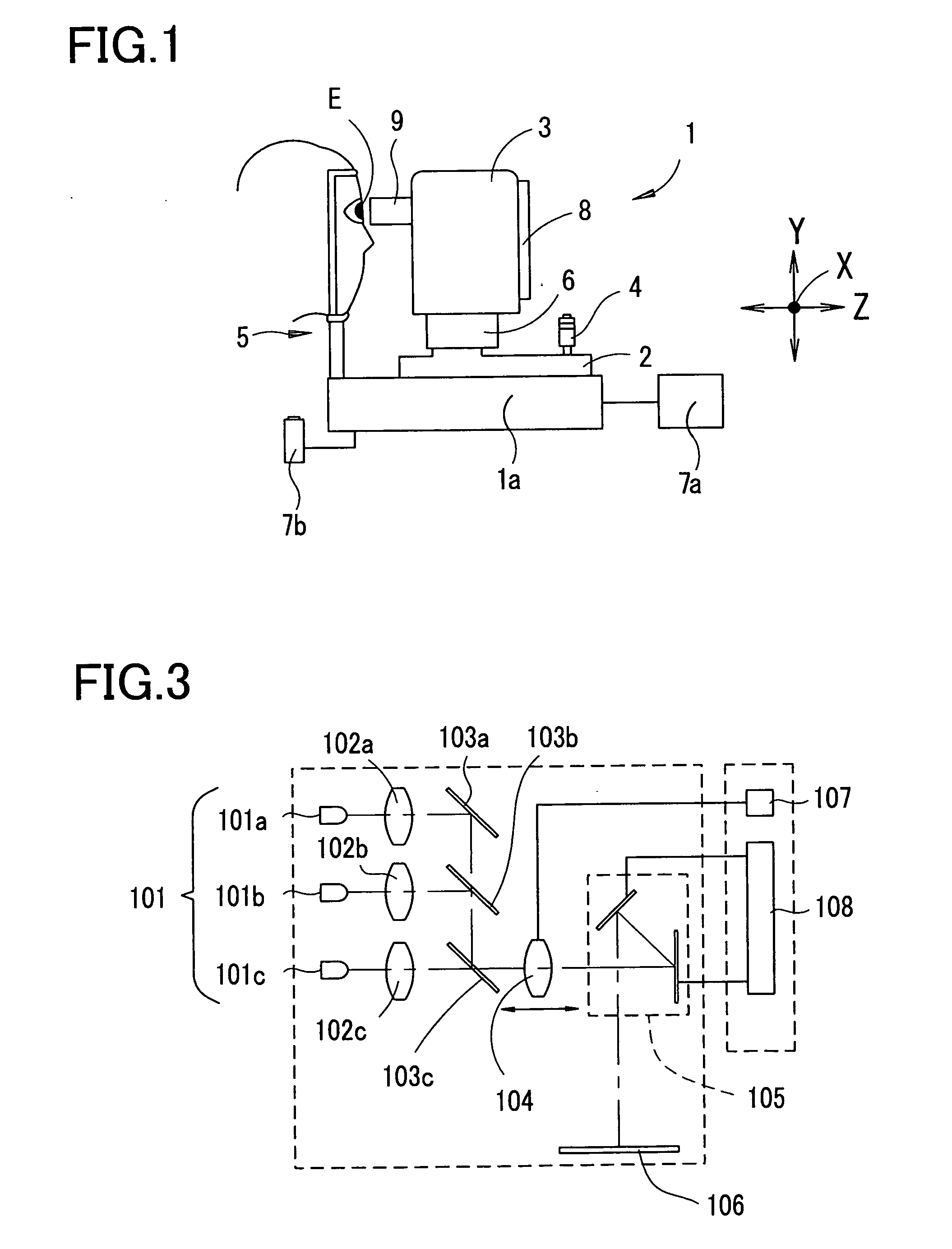
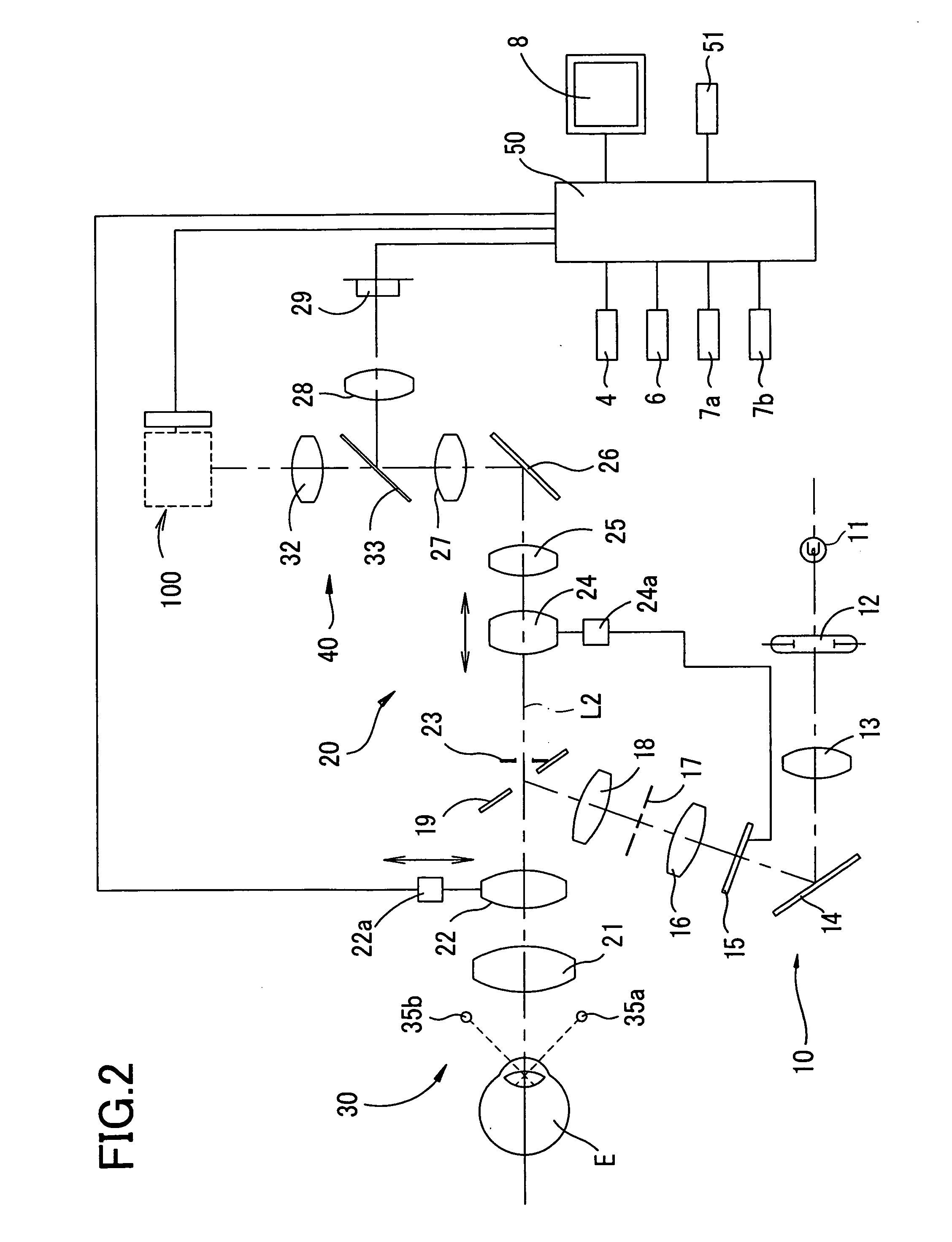
[0015]A detailed description of a preferred embodiment of the present invention will now be given referring to the accompanying drawings. The following example exemplifies an ophthalmic apparatus having the function of observing and photographing an eye fundus, the function of measuring a visual field (distribution of sensitivity of vision) based on responses from an examinee, and the function of performing a visual acuity test based on examinee's responses.

[0016]FIG. 1 is an external perspective view of the ophthalmic apparatus. This apparatus 1 includes a base 1a, a movable table 2 provided to be movable relative to the base 1a in right and left direction (X direction) and back and forth (working distance) direction (Z direction), and a photographing unit (a main unit) 3 provided to be movable relative to the movable table 2 in the right and left direction (X direction), in up and down direction (Y direction), and the back and forth direction (X direction), and a head supporting u...


PUM


Abstract

An ophthalmic apparatus includes: a fundus observation optical system for observing a fundus; a target presenting device including a scanning member for two-dimensionally scanning a visible laser beam emitted from a laser source, the device being configured to control emission of the laser source during two-dimensional scanning by the scanning member to project predetermined target on the fundus under observation through the fundus observation optical system; and control means to change an irradiation diameter of the laser beam by inserting / removing an optical member into / from an irradiation optical path of the laser beam or moving the optical member in an axial direction and to change resolution of the target by changing each scan range of the laser beam by the scanning member according to the changed irradiation diameter of the laser beam. Accordingly, in the ophthalmic apparatus used in close and face-to-face position to an examinee, the size and shape of a target to be presented can be easily set. A test target with high resolution unrealizable by a conventional LCD can be presented.

Description

CROSS-REFERENCE TO RELATED APPLICATIONS[0001]This application is based upon and claims the benefit of priority from the prior Japanese Patent Application No. 2010-153470, filed on Jul. 5, 2010, the entire contents of which are incorporated herein by reference.TECHNICAL FIELD[0002]The present invention relates to an ophthalmic apparatus used for examining examinee's eyes.BACKGROUND ART[0003]Conventional ophthalmic apparatus to be used in a close and face-to-face position to an examinee includes an electronic device such as an LCD (a liquid crystal display). This apparatus is configured to perform observation and photographing of eye fundus through a fundus observation and photographing optical system while having the examinee gaze at a fixation target displayed on the LCD. Further, there is an ophthalmic apparatus adapted to display a visual field test target for visual field test in a position on the LCD other than a position in which the fixation target appears. Thus, a single appa...

Claims


Application Information

Patent Timeline
Patent Type & Authority Applications(United States)
IPC IPC(8): A61B3/12A61B3/028A61B3/024
CPCA61B3/103A61B3/1025A61B3/14
Inventor KONDOH, NAOYUKI
Owner NIDEK CO LTD
Learn More