

Performance apparatus and electronic musical instrument
a technology of electronic musical instruments and performance apparatus, which is applied in the direction of instruments, electrophonic musical instruments, measurement devices, etc., can solve the problems of performance apparatus and it is not easy for a player to change musical tones as he or she plays
- Summary
- Abstract
- Description
- Claims
- Application Information
AI Technical Summary
Benefits of technology
Problems solved by technology
Method used
Image

Examples
first embodiment
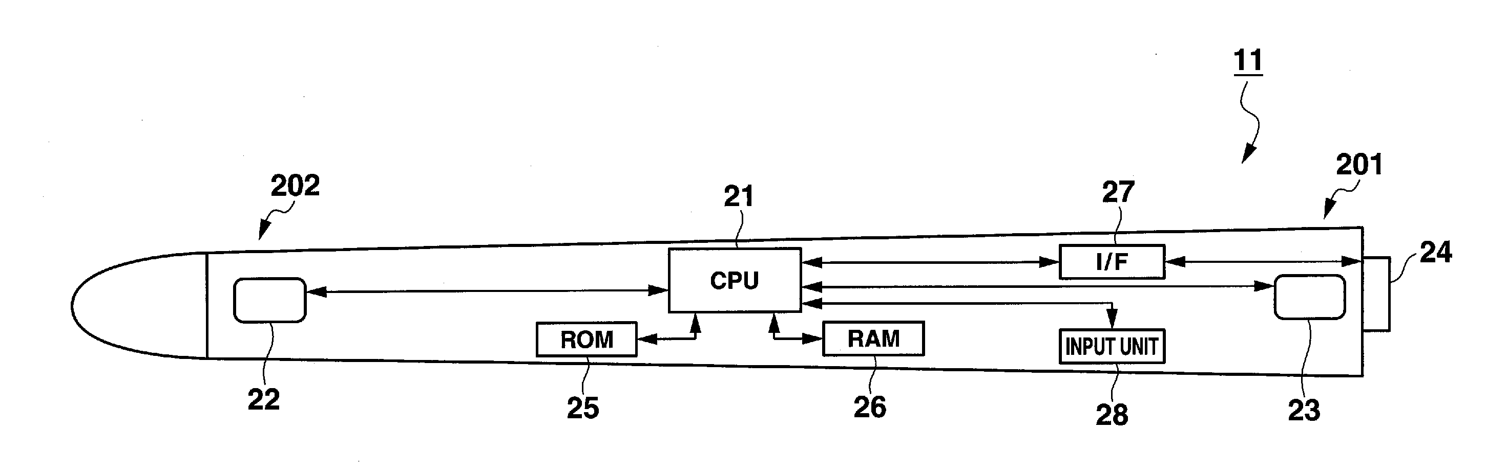
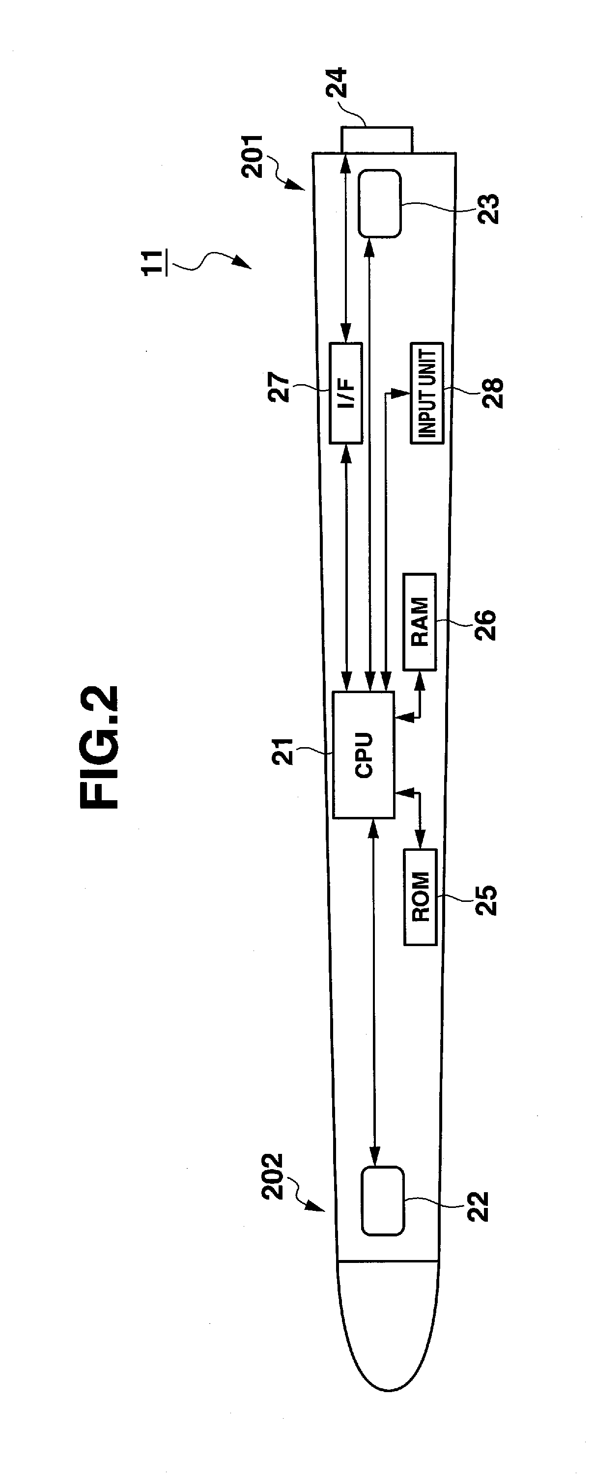
[0042]FIG. 2 is a block diagram of a configuration of the performance apparatus 11 in the invention. In the performance apparatus 11 shown in FIG. 2, the portion (Refer to Reference Number: 201) of the performance apparatus 11 to be held or gripped by the player is called “base”, and the portion (Refer to Reference Number: 202) of the performance apparatus 11 opposite to the base is called “head”. As shown in FIG. 2, the performance apparatus 11 is provided with the first acceleration sensor 22 on the head and the second acceleration sensor 23 on the base, which the player holds or gripes with his or her hand. The acceleration sensors 22 and 23 are 3-dimensional sensors of a capacitance type and / or of a piezoresistive type. The 3-dimensional acceleration sensors 22 and 23 are able to output components of acceleration-sensor values representing acceleration, which are yielded in the base and head in three axial directions such as in X, Y and Z-direction, respectively, when the perfor...
second embodiment
[0094]FIG. 13 is a flow chart of an example of a process to be performed in the performance apparatus 111 according to the CPU 21 of the performance apparatus 111 performs an initializing process at step 1301, clearing data in RAM 26. CPU 21 judges at step 1302 whether or not the switch in the input unit 28 has been operated to give an instruction of setting reference information. When it is determined YES at step 1302, CPU 21 performs a reference setting process at step 1303.
[0095]FIG. 14 is a flow chart of an example of the reference setting process performed in the performance apparatus 111 according to the second embodiment. In the reference setting process, as the reference value (reference-offset value) is set or obtained the longitudinal direction of the performance apparatus 111 held at the time when the player turns on a setting switch (not shown) of the input unit 28 of the performance apparatus 111. CPU 21 obtains a sensor value of the geomagnetic sensor 29. Using the ob...
third embodiment
[0107]FIG. 20 is a flowchart of an example of the reference setting process performed in the performance apparatus 211 according to the In the reference setting process, an angular-rate sensor value is obtained at the time when the player turns on the setting switch (not shown) in the input unit 28 of the performance apparatus 211. More specifically, CPU 21 obtains a sensor value from the angular-rate sensor 30 at step 2001.
[0108]CPU 21 judges at step 2002, whether or not the setting switch of the input unit 28 has been turned on. When it is determined YES at step 2002, CPU 21 stores in RAM 26 the angular-rate sensor value as the reference sensor value ωp (step 2003). Then, CPU 21 judges at step 2004 whether or not the finishing switch (not shown) of the input unit 28 has been turned on. When it is determined NO at step 2004, CPU 21 returns to step 2001. Meanwhile, when it is determined YES at step 2004, CPU 21 finishes the reference setting process. In the above reference setting ...
PUM
 Abstract
Description
Claims
Application Information