Instrument caddy with anti-magnetic shield

a technology of anti-magnetic shield and instrument caddy, which is applied in the direction of magnetic body, wash stand, packaged goods type, etc., can solve the problems of poor adaptation, difficult to remove instruments/meters, and difficult to adjust to the environment. , to achieve the effect of increasing the ergonomic design of the instrument and increasing the ease of handling

Inactive Publication Date: 2008-06-24
SLAPPAY ROBERT
View PDF15 Cites 66 Cited by
  • Summary
  • Abstract
  • Description
  • Claims
  • Application Information

AI Technical Summary

Benefits of technology

[0007]The instrument caddy and protection device of the present invention is advantageously fabricated from a plastic material such as, for example, polyvinyl, polyether, polyester, polystyrene of polyacrylate plastics. However, certain preferred embodiments of the present invention advantageously utilize a housing fabricated from a resilient rubber compound. Such compounds display elastic properties that allow the retentive pocket to be configured so as to be slightly smaller than the instrument the caddy is designed to hold. The resilient nature of rubber compounds, such as, for example, natural, nitrile or silicon rubber compounds, enable lateral walls of the retentive pocket to stretch so as to enable initial entry of an instrument within the confines thereof. Thereafter, the resilient rubber compound enables the pocket wall to return to their initial dimensions so as to bias against and retain the instrument therewithin.
[0009]The instrument caddy and protection device of the present invention is configured, in certain preferred embodiments thereof, to contain cutouts located at one or both of the two end panels. These cutouts, as described in more detail below, enable the passage of hand straps, cable connectors and other attachments through the housing thereby enabling instruments to be fully functional while remaining within the caddy. In addition, it is preferred that at least one side panel of the housing is configured to include finger recesses therein. Such recesses increase the ease of handling and carrying the instrument caddy and protection device of the present invention while also increasing the ergonomic design thereof.

Problems solved by technology

Often these instruments are utilized in an environment posing hazzards to the instrument itself such as, for example, shock, vibration, heat and, very often, accidental dropping of the unit.
These instruments may be placed in very harsh environments such as, for example, within an engine bay, or on top of a heating or air conditioning unit during use.
However, such holsters did not provide a suitable and practical means of stabilizing the instrument during actual use.
In addition, most of the instrument holsters of the past have been made for a specific meter or provide a relatively poor adaptation requiring removal of the instrument / meter during actual use.
Once the instrument is removed from the holster for use, the meters are, of course, vulnerable to damage.
In addition to the heat and vibration relatively delicate meters are exposed to, strong magnetic fields can alter the readings of such devices.
Prolonged exposure to strong magnetic fields can also damage electronic measuring tools.
In addition, power supplies, power lines, transformers, generators and alternators can all effect delicate electronic circuitry.

Method used


Image

  • Instrument caddy with anti-magnetic shield
  • Instrument caddy with anti-magnetic shield
  • Instrument caddy with anti-magnetic shield

Examples


Embodiment Construction

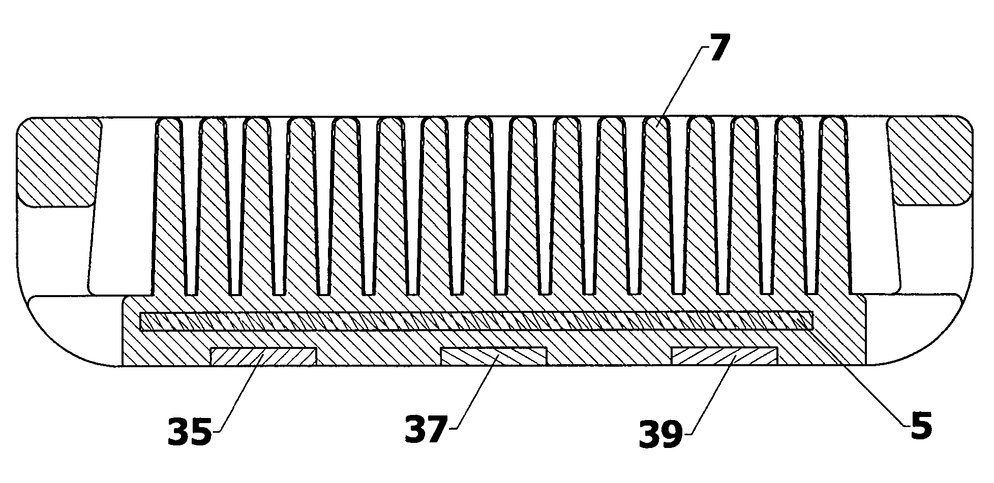
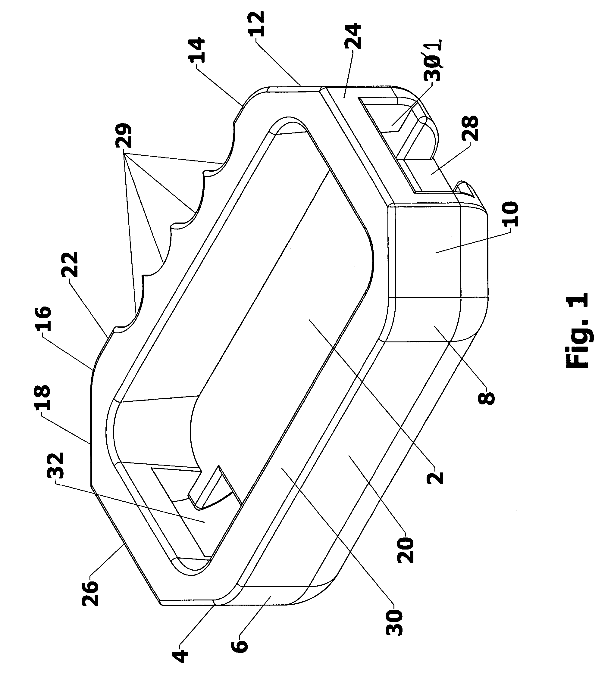
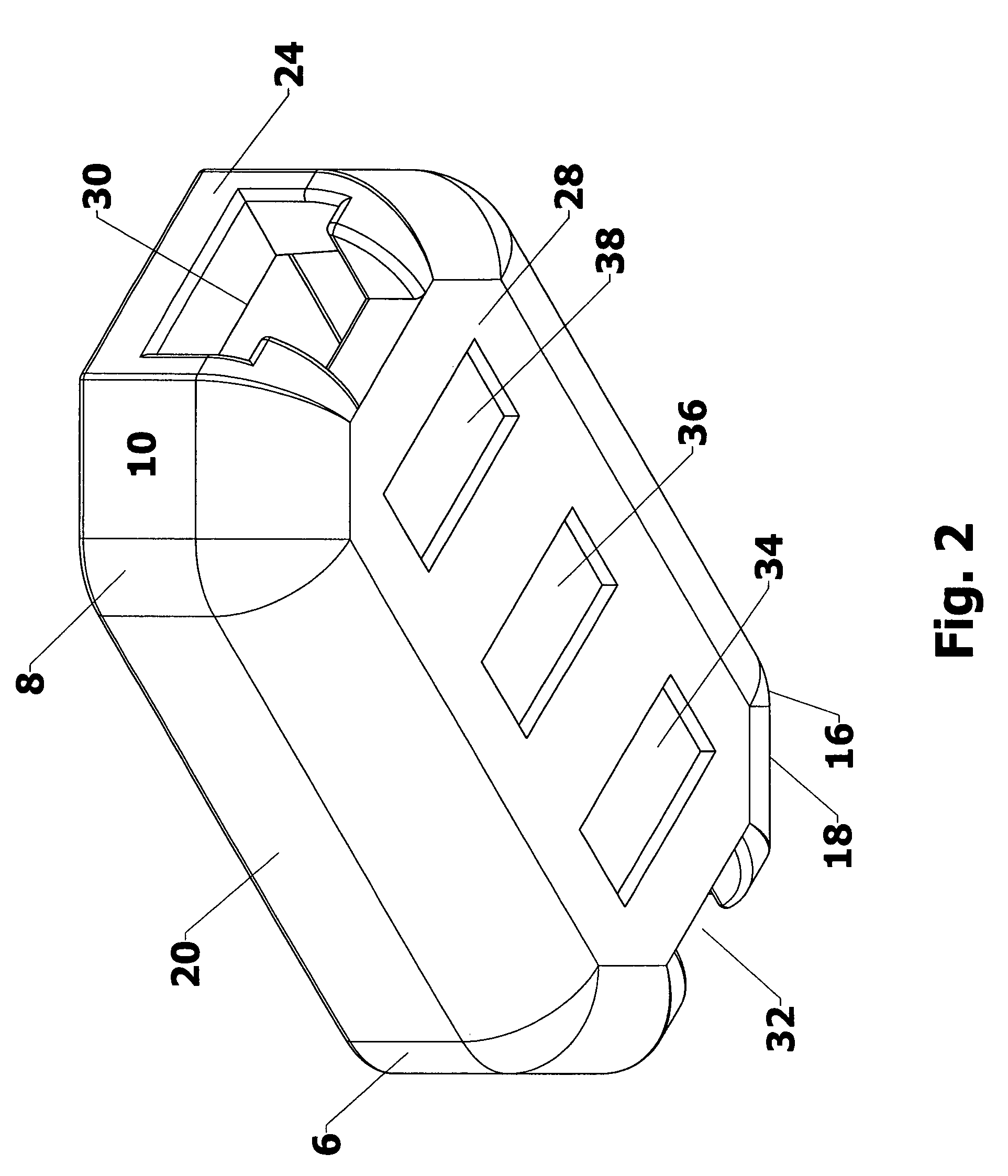
[0017]FIGS. 1-3 illustrate a first preferred embodiment of the instrument protection and caddy device of the present invention. The device is comprised of an outer housing at least one magnet and a recessed retentive pocket. In the first preferred embodiment illustrated in the figures, the outer housing includes, surrounds and defines a recessed instrument receiver pocket. The retentive pocket (or as it may be equally referred to as “instrument receiver pocket”) is especially configured so as to provide for a retentive fit of an instrument for which it is intended to be used. What is meant by the term retentive fit, is that close adaptation between the inside dimensions of the receiver pocket and outside dimensions of the instrument to be placed therein so that when the pocket faces downward (in the direction of the floor and in line with gravitational forces that might otherwise displace the instrument from the caddy) the instrument remains within the caddy.

[0018]In the embodiment ...


PUM

PropertyMeasurementUnit
anti-magneticaaaaaaaaaa
dimensionsaaaaaaaaaa
magnetic forceaaaaaaaaaa

Abstract

An instrument caddy and protection device is disclosed having a retentive pocket configured to closely adapted to, retain against displacement and protect an electronic instrument therein such as, for example, a multi-meter. The instrument caddy includes at least one magnet that enables the caddy to hold an instrument against a metallic surface during use while simultaneously protecting the instrument against breakage. Alternate embodiments of the caddy are disclosed wherein the retentive pocket is initially filled with sectioned and removable foam insert material enabling custom sizing of the retentive pocket so as to adapt to an instrument having given dimensions. In addition, preferred embodiments of the caddy provide for passageways for test cables and / or instrument straps to be attached to the instrument while it is held with the retentive pocket. Further embodiments are disclosed which include a magnetic shield incorporated within the caddy and positioned between the retentive pocket and the at least one magnet so as to protect the instrument against magnetic interference from either the caddy magnet(s) or interference originating from the surface upon which the caddy is placed.

Description

TECHNICAL FIELD[0001]This disclosure relates to the field of electronic instrument cases and holsters. More specifically, this disclosure relates to electronic instrument holsters demonstrating the ability to position and safely hold such instrument during use.BACKGROUND OF THE ART[0002]Multi-meters, automotive test meters and assorted electronic specialty meters are in common use in the work place. Often these instruments are utilized in an environment posing hazzards to the instrument itself such as, for example, shock, vibration, heat and, very often, accidental dropping of the unit. These instruments may be placed in very harsh environments such as, for example, within an engine bay, or on top of a heating or air conditioning unit during use. In the past, holsters enabling service technicians to clip such devices to their belts were provided. However, such holsters did not provide a suitable and practical means of stabilizing the instrument during actual use. In addition, most o...

Claims


Application Information

Patent Timeline
Patent Type & Authority Patents(United States)
IPC IPC(8): B65D85/38H01F7/20
CPCA45F5/00B25H5/00Y10S206/818
Inventor SLAPPAY, ROBERT
Owner SLAPPAY ROBERT
Why Eureka
Try Eureka