
Power transmission control device, power transmission device, electronic instrument, and non-contact power transmission system

a technology of power transmission control and control device, which is applied in the direction of safety/protection circuit, transportation and packaging, inductance, etc., can solve the problem that the accuracy of foreign objects cannot be improved to a satisfactory level

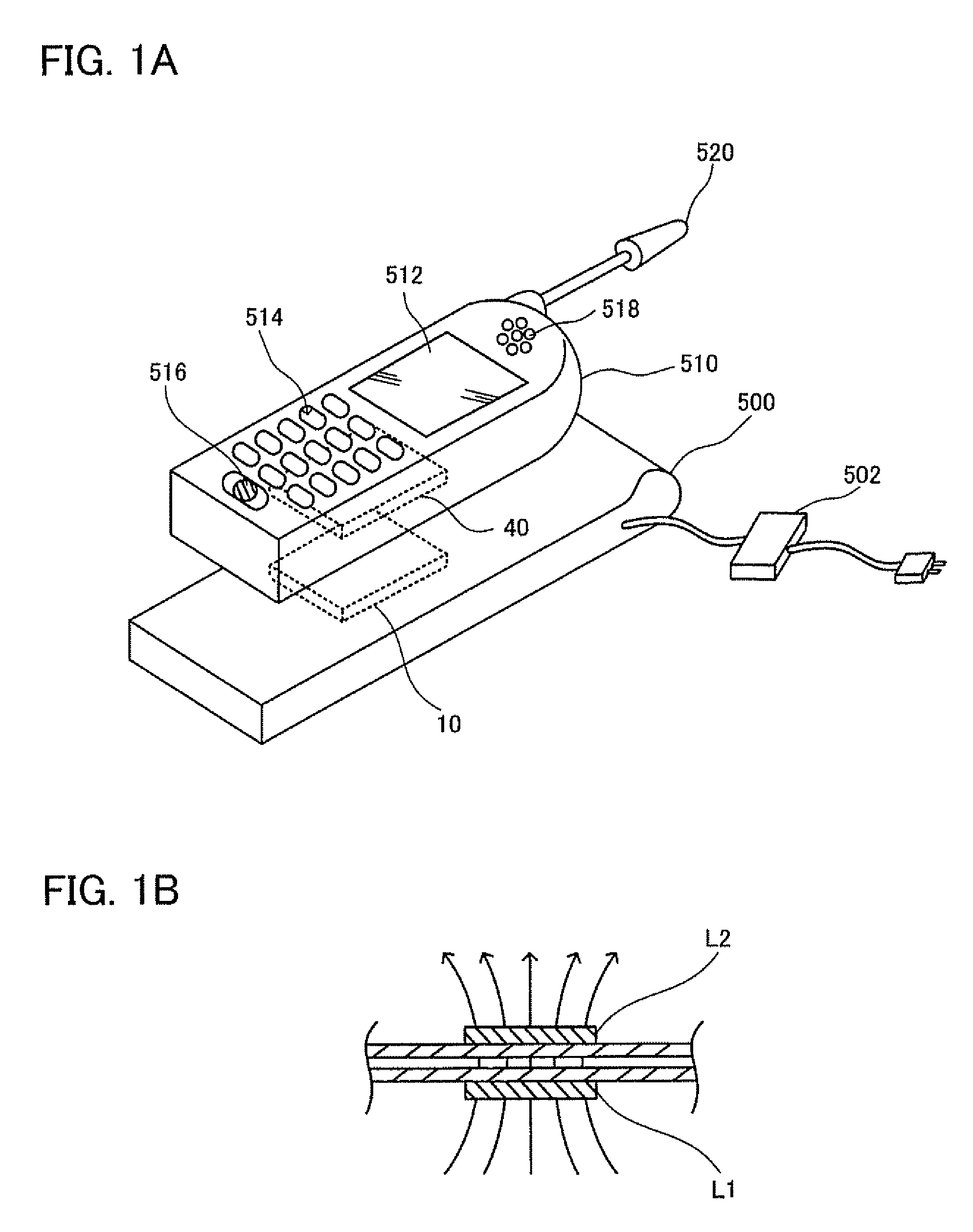
Active Publication Date: 2010-10-12
CHAMIRAUX MANAGEMENT LLC
View PDF12 Cites 66 Cited by
  • Summary
  • Abstract
  • Description
  • Claims
  • Application Information

AI Technical Summary

Benefits of technology

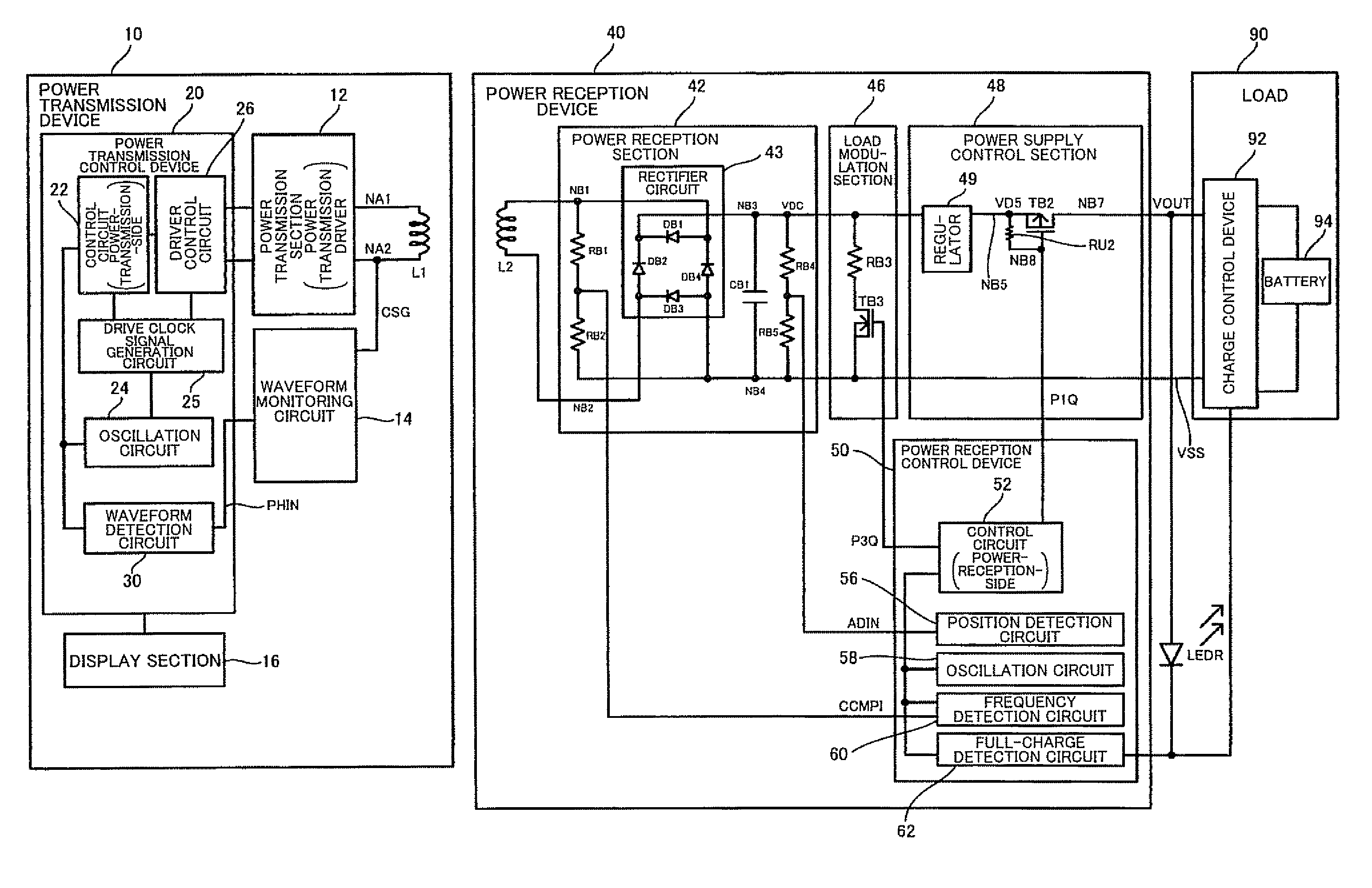
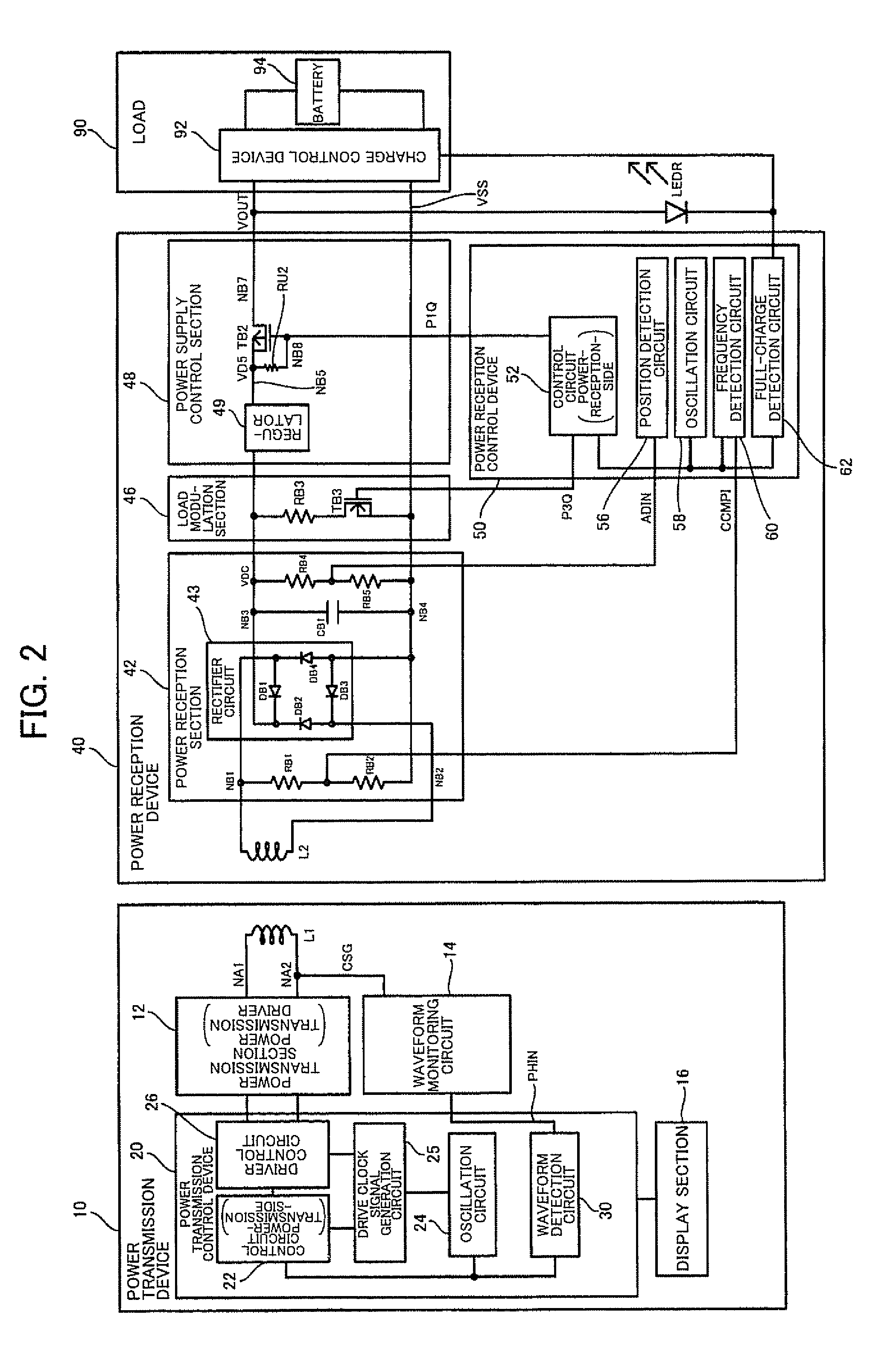
"The invention provides a power transmission control device and system for non-contact power transmission. The device includes a drive clock signal generation circuit, a driver control circuit, a waveform detection circuit, and a control circuit for foreign object detection. The system includes a power transmission device and a power reception device, which are connected through a primary coil and secondary coil. The drive clock signal generation circuit generates a drive clock signal to specify the frequency of the primary coil, and the driver control circuit generates a driver control signal based on the drive clock signal and outputs it to the transmission driver. The waveform detection circuit detects changes in the induced voltage signal of the primary coil, and the control circuit performs foreign object detection based on the detection result. The drive clock signal generation circuit also outputs a foreign object detection frequency during foreign object detection. The technical effects of the invention include improved power transmission efficiency, improved foreign object detection, and improved power transmission control."

Problems solved by technology

Therefore, the foreign object detection accuracy cannot be improved to a satisfactory level.

Method used


Image

  • Power transmission control device, power transmission device, electronic instrument, and non-contact power transmission system
  • Power transmission control device, power transmission device, electronic instrument, and non-contact power transmission system
  • Power transmission control device, power transmission device, electronic instrument, and non-contact power transmission system

Examples


Embodiment Construction

[0042]Several aspects of the invention may provide a power transmission control device, a power transmission device, an electronic instrument, and a non-contact power transmission system capable of improving the foreign object detection accuracy.

[0043]According to one embodiment of the invention, there is provided a power transmission control device provided in a power transmission device included in a non-contact power transmission system, the non-contact power transmission system transmitting power from the power transmission device to a power reception device by electromagnetically coupling a primary coil and a secondary coil to transmit the power to a load of the power reception device, the power transmission control device comprising:

[0044]a drive clock signal generation circuit that generates a drive clock signal that specifies a drive frequency of the primary coil;

[0045]a driver control circuit that generates and outputs a driver control signal based on the drive clock signal...


PUM

PropertyMeasurementUnit
voltageaaaaaaaaaa
currentaaaaaaaaaa
currentaaaaaaaaaa

Abstract

A power transmission control device provided in a power transmission device of a non-contact power transmission system includes a drive clock signal generation circuit that generates a drive clock signal specifying a drive frequency of a primary coil, a driver control circuit that generates a driver control signal based on the drive clock signal, and outputs the driver control signal to a transmission driver, a waveform detection circuit that detects a change in waveform of an induced voltage signal of the primary coil, and a control circuit that performs foreign object detection based on a detection result of the waveform detection circuit. The drive clock signal generation circuit outputs the drive clock signal set at a foreign object detection frequency during foreign object detection, the foreign object detection frequency being a frequency differing from a normal power transmission frequency.

Description

[0001]Japanese Patent Application No. 2007-171346 filed on Jun. 29, 2007 and Japanese Patent Application No. 2007-184270 filed on Jul. 13, 2007, are hereby incorporated by reference in their entirety.BACKGROUND OF THE INVENTION[0002]The present invention relates to a power transmission control device, a power transmission device, an electronic instrument, a non-contact power transmission system, and the like.[0003]In recent years, non-contact power transmission (contactless power transmission) that utilizes electromagnetic induction to enable power transmission without metal-to-metal contact has attracted attention. As application examples of non-contact power transmission, charging a portable telephone, charring a household appliance (e.g., cordless telephone handset), and the like have been proposed.[0004]JP-A-2006-60909 discloses related-art non-contact power transmission. According to the technology disclosed in JP-A-2006-60909, a power transmission device (primary-side instrume...

Claims


Application Information

Patent Timeline
Patent Type & Authority Patents(United States)
IPC IPC(8): H01F27/42H01F37/00H01F38/00
CPCH02J7/025H01F38/14H02J50/10H02J7/00045H02J7/00304H02J50/12H02J50/80H02J50/90H02J50/60
Inventor IISAKA, KENJIN, MIKIMOTO
Owner CHAMIRAUX MANAGEMENT LLC
Learn More