Illumination device and manufacturing method therefor, display device, and electronic instrument

a technology of a display device and a manufacturing method, which is applied in the direction of semiconductor devices, instruments, optics, etc., can solve the problems of reducing illumination efficiency, leaking light, and part of the light emitted from the light source not traveling

Inactive Publication Date: 2002-09-05
ELEMENT CAPITAL COMMERCIAL CO PTE LTD
View PDF0 Cites 67 Cited by
  • Summary
  • Abstract
  • Description
  • Claims
  • Application Information

AI Technical Summary

Problems solved by technology

However, because reflective type liquid crystal display devices are difficult to view in dark locations, a reflective type of liquid crystal display device provided with a front light (illumination device) on the viewer's side of the liquid crystal display panel has been proposed.
However, the problem when using the above conventional front light is that a part of the light emitted from the light source does not travel towards the liquid crystal display panel, but instead travel from the surface of the light guide plate on the vie...

Method used


Image

  • Illumination device and manufacturing method therefor, display device, and electronic instrument
  • Illumination device and manufacturing method therefor, display device, and electronic instrument
  • Illumination device and manufacturing method therefor, display device, and electronic instrument

Examples


third embodiment

[0131] Third Embodiment

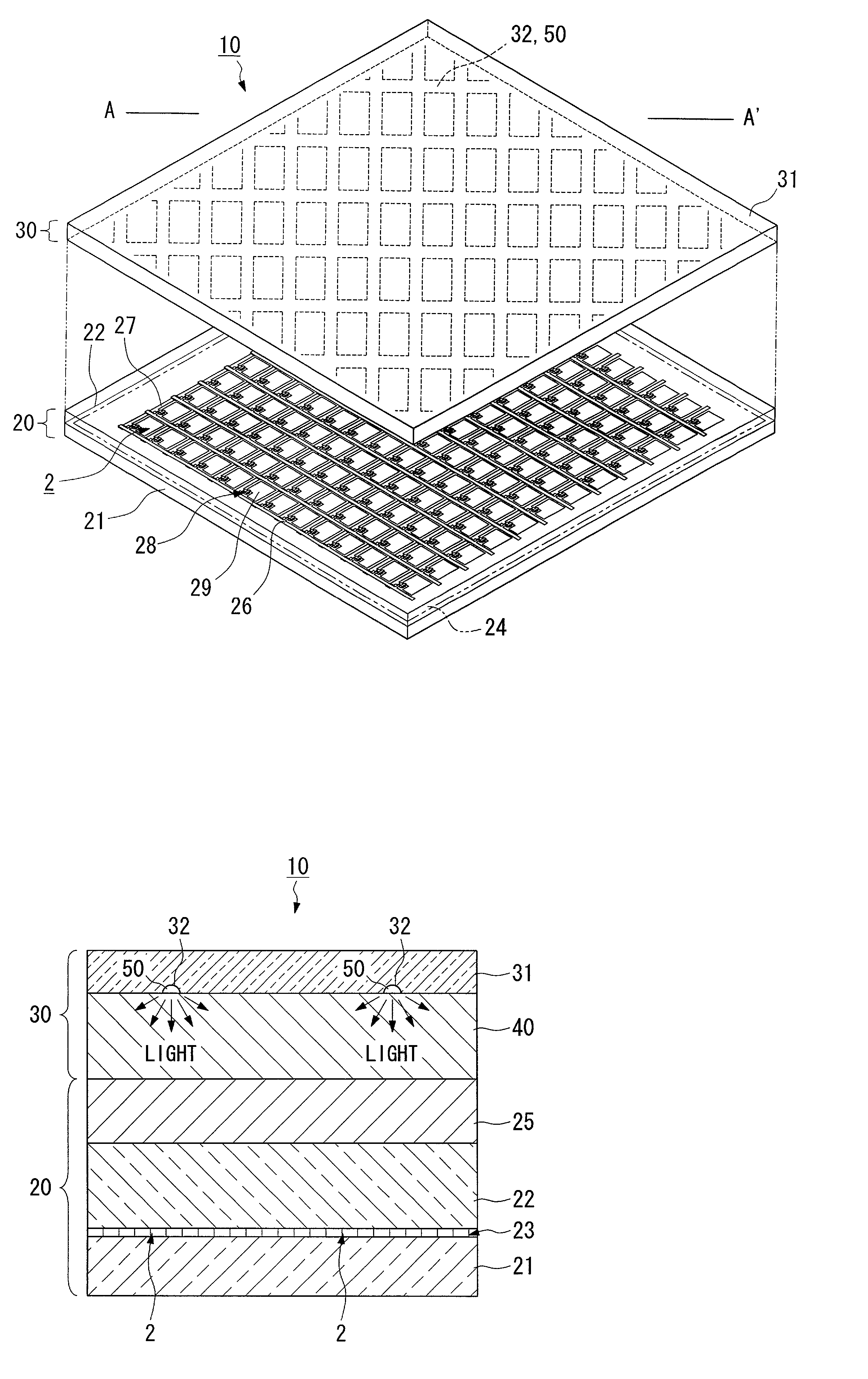
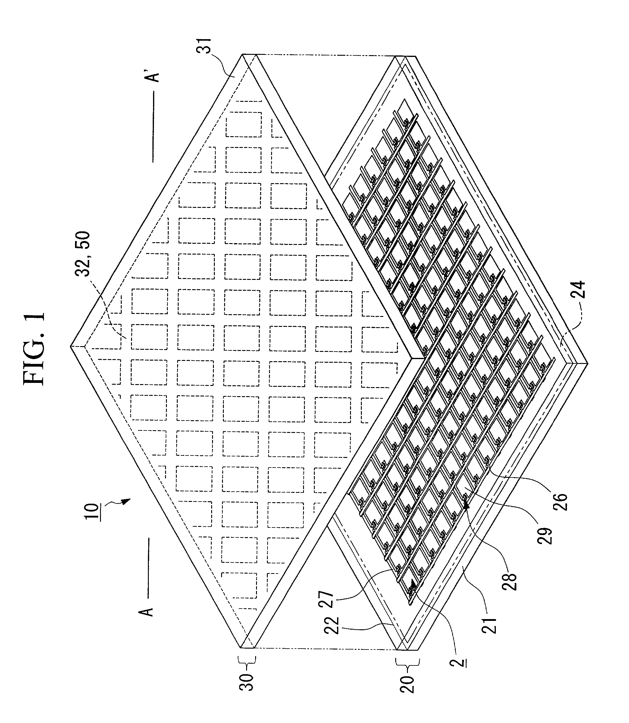
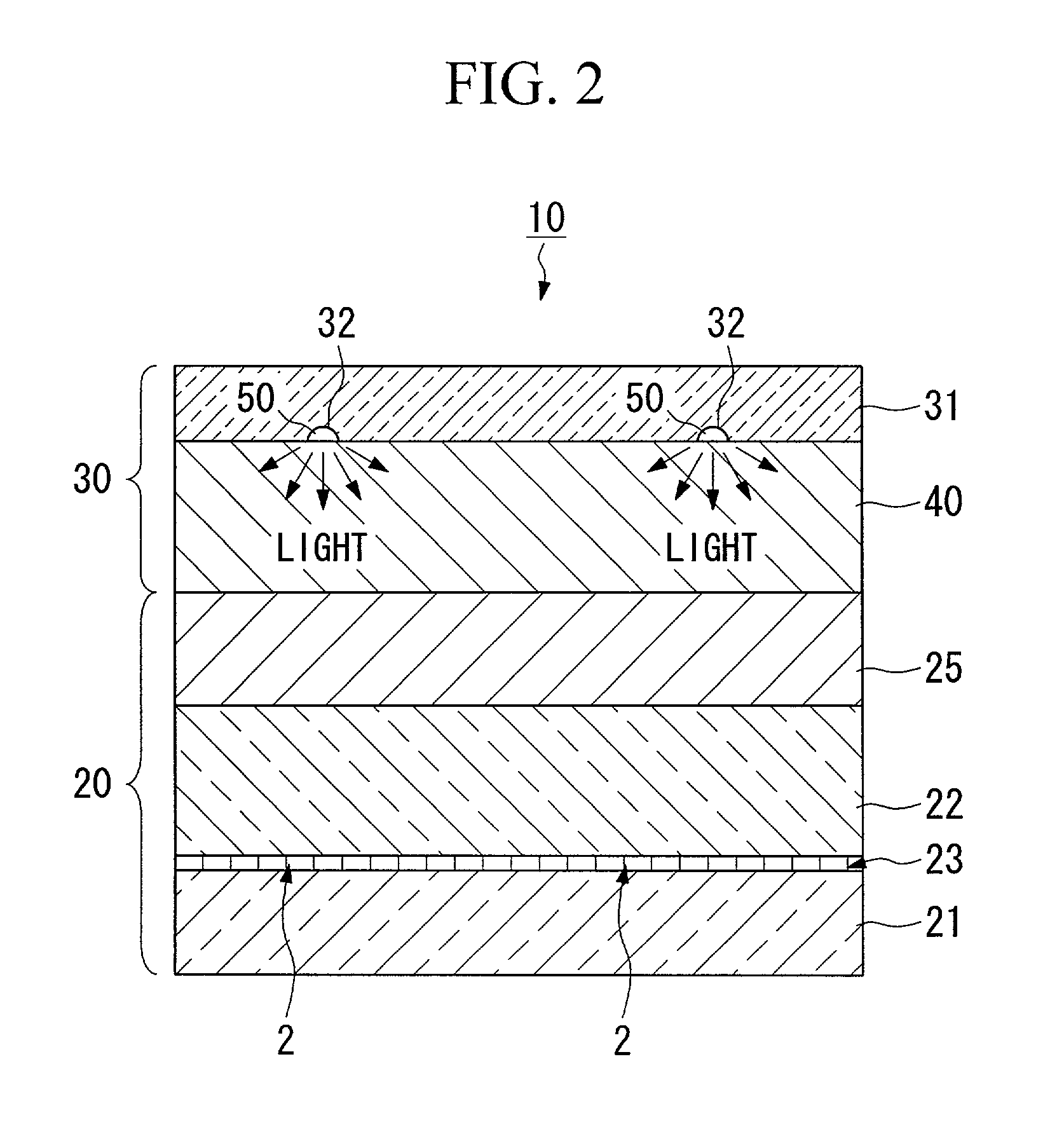
[0132] A description will now be given based on FIGS. 10 to 13 of the structures of the illumination device of the present embodiment and a display device provided with this illumination device. FIG. 10 is a schematic perspective view showing an exploded view of the display device of the present embodiment. FIG. 11 is a partial schematic cross sectional view of the display device of the present embodiment. FIG. 12 is a partial schematic cross sectional view showing in enlargement the electroluminescent element described below. FIG. 13 is a schematic plan view showing the relationship between the pattern of the pixels of the display device and the pattern of the electroluminescent element described below. Note that FIGS. 11 and 12 are cross sections of the display device of the present embodiment with the cross section taken along the line A-A' shown in FIG. 10.

[0133] In the present embodiment, the example of the display device that is described is provided wit...


PUM


Abstract

An illumination device is provided that reduces the amount of light leaked and thus improves illumination efficiency. Electroluminescent elements are formed on one surface of a transparent substrate. The electroluminescent elements are provided with at least a transparent electrode, a light emitting layer, and a reflective electrode in order from the outgoing surface of the transparent substrate. Concavities are formed on one surface of the transparent substrate and at least the reflective electrode is formed in the concavities. Alternatively, electroluminescent elements are arranged in a planar configuration, and the intervals between the electroluminescent elements and the intervals between the pixels are set so as not to be equal to each other, and also the directions in which the electroluminescent elements extend and the directions in which the pixels are aligned are set so as not to be parallel to each other.

Description

[0001] 1. Field of the Invention[0002] The present invention relates to an illumination device and a manufacturing method therefor, a display device, and an electronic instrument and, in particular, to an illumination device that is advantageous when formed as a front light placed on the viewing side of a display device, and to a display device whose viewing side is provided with this illumination device, as well as to an electronic instrument provided with this display device.[0003] 2. Description of the Related Art[0004] Conventionally, a reflective type of liquid crystal display device (electro-optical device) is known in which exterior light such as sunlight shines into the viewing side of a liquid crystal display panel, is reflected inside the liquid crystal display panel, and is then transmitted to the viewer's side. However, because reflective type liquid crystal display devices are difficult to view in dark locations, a reflective type of liquid crystal display device provid...

Claims


Application Information

Patent Timeline
IPC IPC(8): G02F1/13357H01L51/52
CPCG02F1/133603G02F2001/133616H01L51/52H01L51/5262G02F1/133616H10K50/80H10K50/85G02F1/1335
Inventor YOSHIDA, SHOHEIIISAKA, HIDEHITOSAKATA, HIDEFUMITAKEUCHI, TETSUHIKO
Owner ELEMENT CAPITAL COMMERCIAL CO PTE LTD
Why Eureka
Try Eureka