

Slot antenna, electronic apparatus, and method for manufacturing slot antenna
a technology of electronic equipment and slot antennas, applied in the direction of slot antennas, antenna details, antennas, etc., can solve the problems of reducing the distance between each antenna and the metal, increasing the number and sophistication of wireless functions mounted in portable wireless terminals, and reducing the size and thickness of antennas, etc., to achieve small mounting space and multi-resonance
- Summary
- Abstract
- Description
- Claims
- Application Information
AI Technical Summary
Benefits of technology
Problems solved by technology
Method used
Image

Examples
first exemplary embodiment
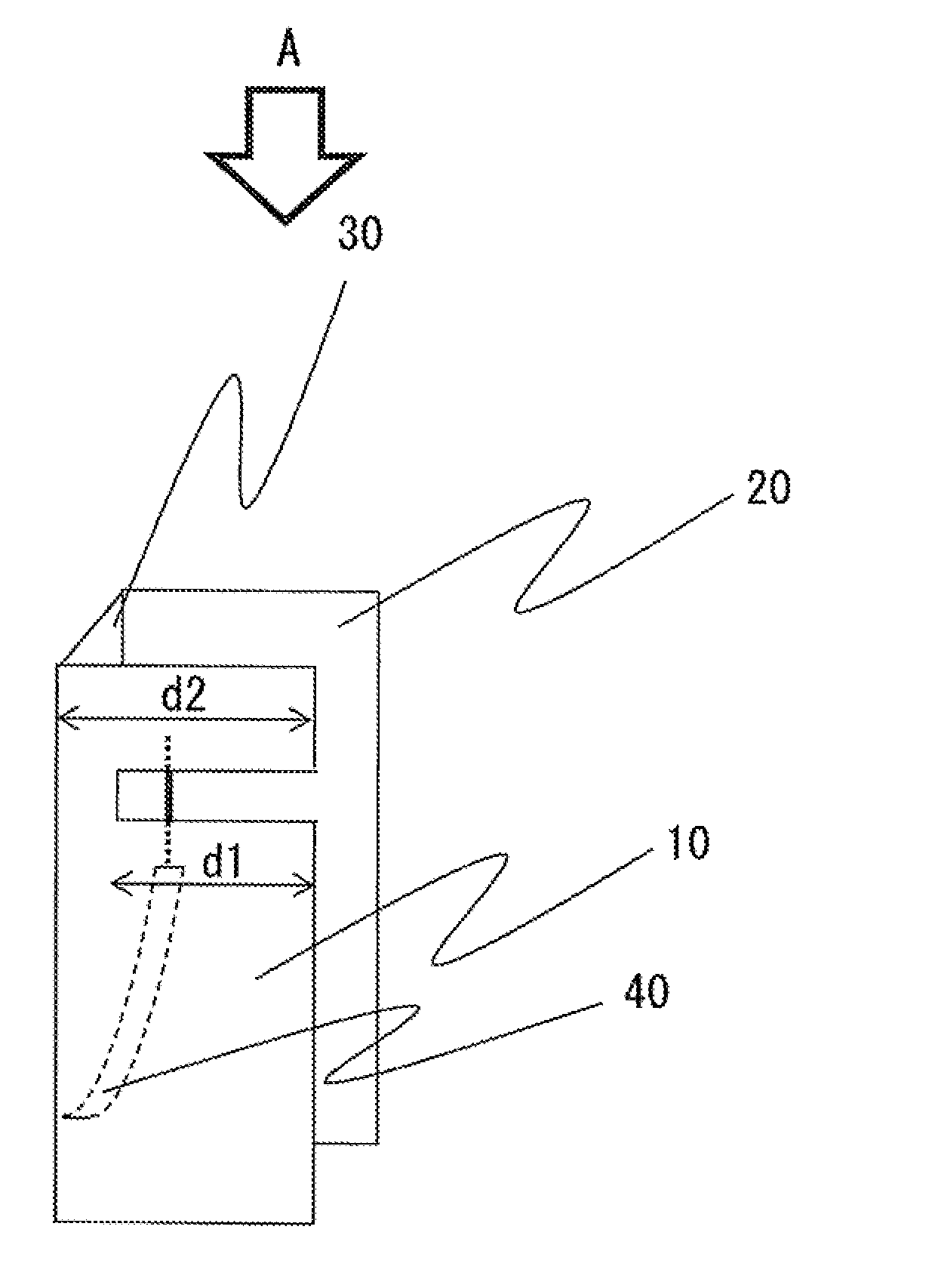
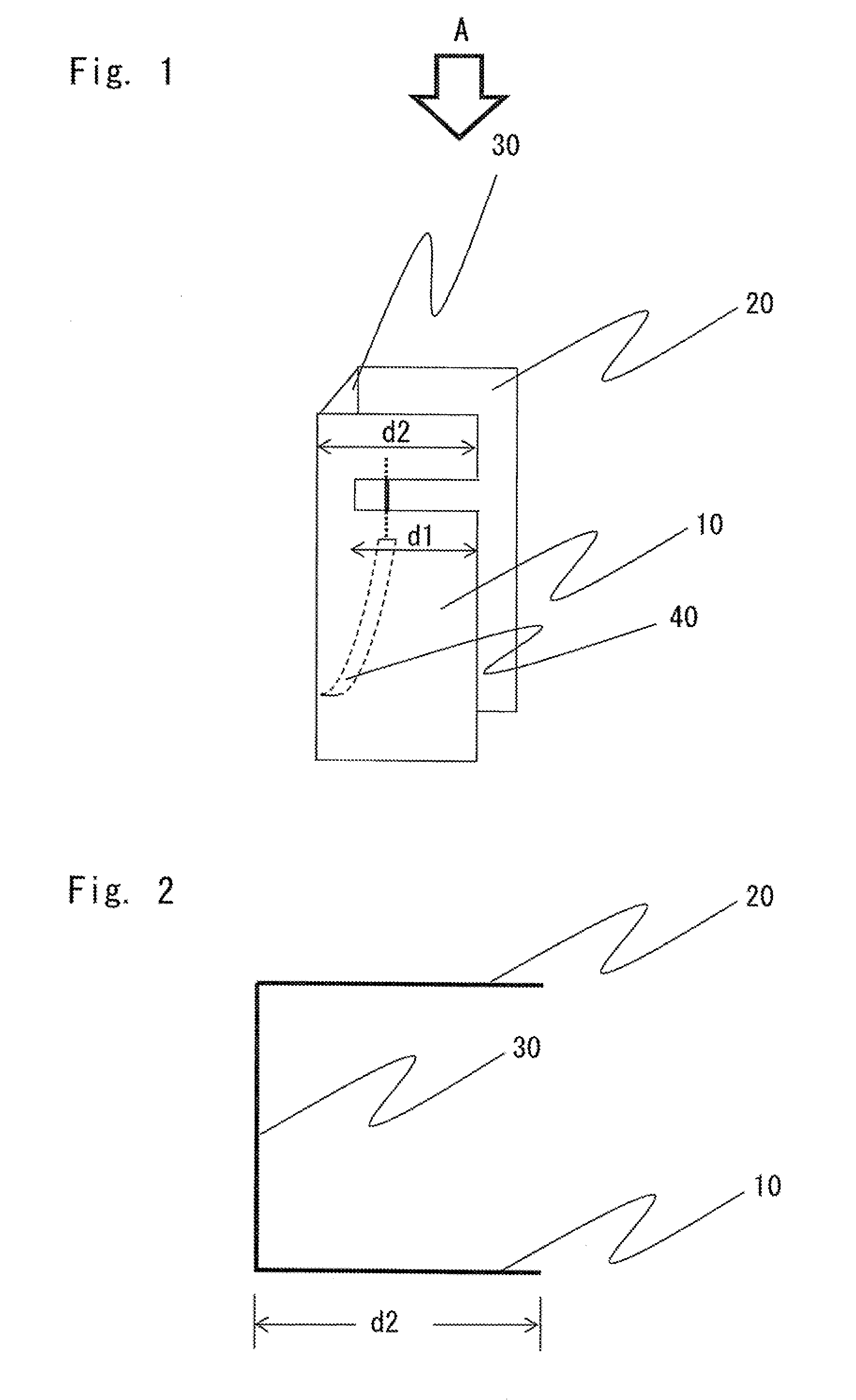
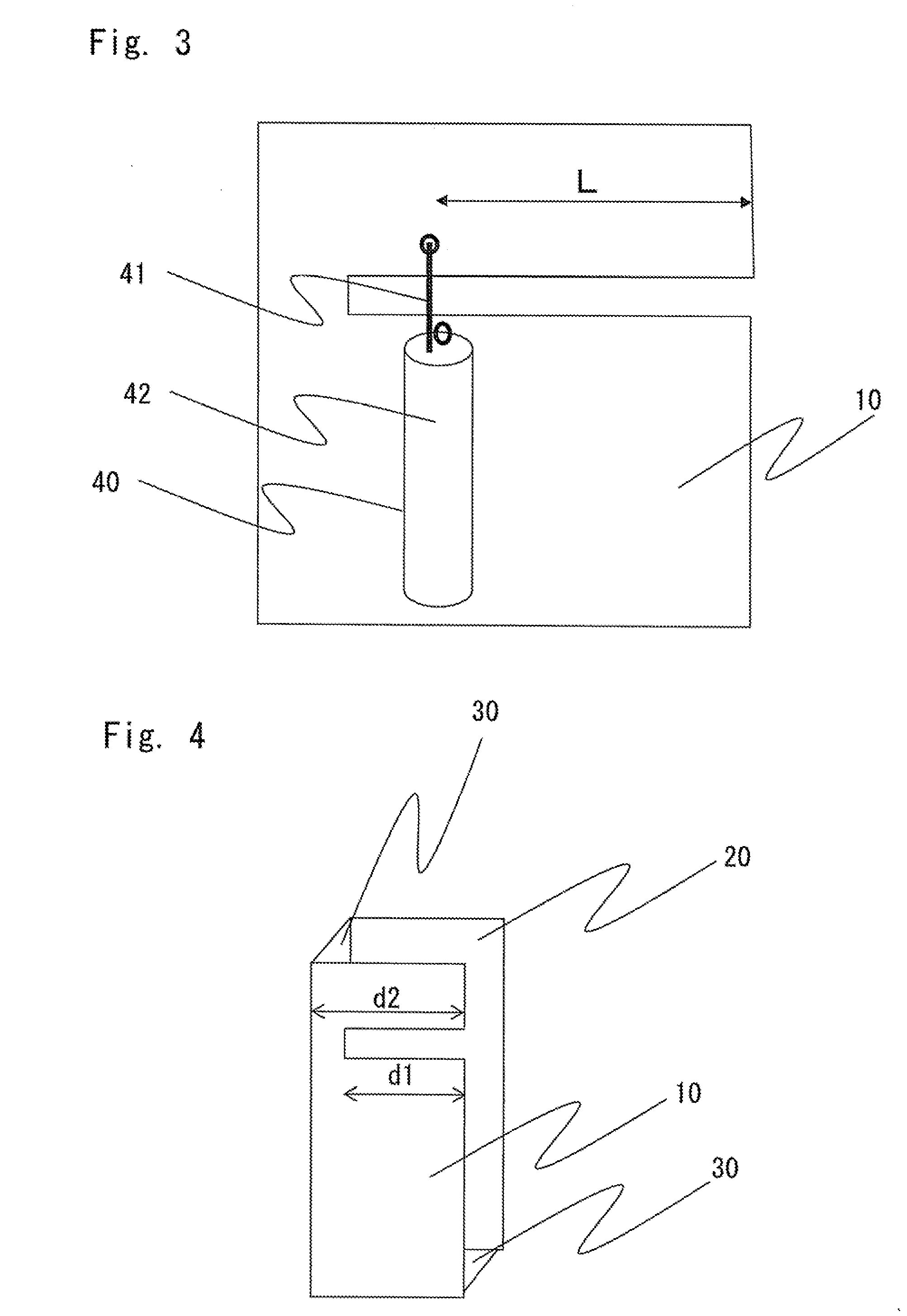
[0028]Exemplary embodiments of the present invention will be described below with reference to the drawings. FIG. 1 is a diagram showing a structure of a slot antenna according to a first exemplary embodiment of the present invention. FIG. 2 is a diagram of the slot antenna according to the first exemplary embodiment of the present invention, when viewed from the direction of the arrow “A” in FIG. 1. The slot antenna according to the first exemplary embodiment of the present invention includes conductor plates 10 to 30 and a feeder 40.
[0029]The conductor plate 10 is provided with the feeder 40 and has an elongated notch (hereinafter referred to as “slot”). The slot is formed on one side of the conductor plate 10 and has an open end. Assume herein that the width of the slot is sufficiently smaller than a length d1 of the slot and the length of one side of the conductor plate 10 in the same direction as the length of the slot is represented by d2.
[0030]A conductor plate 20 is disposed...
second exemplary embodiment
[0042]Referring next to FIG. 6, a structure of a slot antenna according to a second exemplary embodiment of the present invention will be described. The feeder 40 is similar to that shown in FIG. 1, so the description thereof is omitted. The slot antenna according to the second exemplary embodiment of the present invention has a feature that a slot is bent at an angle of 90 degrees into an L-shape. The other components are similar to those of the first exemplary embodiment. Assume that the length of a notch extending in the direction of the conductor plate 30 from an open end is represented by d3 and the length of the notch extending in parallel with the conductor plate 30 is represented by d4. In this case, resonance is generated at a frequency, one-quarter of the wavelength of which is equal to the distance represented by d3+d4. Another resonance is generated such that a current is excited along a U-shaped cavity structure formed of the conductor plates 10, 20, and 30, and a stand...
third exemplary embodiment
[0044]Referring next to FIG. 7, a structure of a slot antenna according to a third exemplary embodiment of the present invention will be described. The feeder 40 is similar to that shown in FIG. 1, so the description thereof is omitted. The slot antenna according to the third exemplary embodiment of the present invention has a feature that another notch with an open end is formed at a side near the notch other than one side connected to the third conductor plate and one side having the open end. The newly formed slot is used to adjust the length d2. That is, when a length d5 of the notch is taken into consideration, the distance d2 is expressed as d2+2×d5. As a result, resonance is generated at a frequency, one-quarter of the wavelength of which is equal to the distance represented by d2+2×d5.
[0045]As described above, the use of the slot antenna according to the third exemplary embodiment of the present invention enables arbitrary adjustment of the resonance frequency obtained with ...
PUM
| Property | Measurement | Unit |
|---|---|---|
| Length | aaaaa | aaaaa |
| Shape | aaaaa | aaaaa |
| Frequency | aaaaa | aaaaa |
Abstract
Description
Claims
Application Information