
Fluid pump

a technology of fluid pump and pump body, which is applied in the direction of non-positive displacement fluid engine liquid fuel engine components, etc., can solve the problems of large and therefore most expensive parts in production, and the need for small mounting space, so as to reduce costs and improve efficiency , the effect of simple production

Inactive Publication Date: 2009-05-07
PIERBURG GMBH & CO KG NEUSS
View PDF16 Cites 2 Cited by
  • Summary
  • Abstract
  • Description
  • Claims
  • Application Information

AI Technical Summary

Benefits of technology

[0011]This object is achieved with the characterizing part of the main claim. Thereby, the number of different components and thus the costs are reduced, while a high efficiency is to be realized. Moreover, the connection with a suction-side and a pressure-side pump housing part is simple to make, and little loss occurs. Thus, intake and pressure ports can be integrated in these parts. Further, these are the largest and therefore most expensive parts in the production. Notably, tooling costs are saved. Assembly errors caused by confusing the mounting direction are excluded. The shape of the individual ports facilitates the connection to the axially adjacent housing parts and provides for a steady low-loss transition when the flow is deflected. Mounting into a cooling system is readily realized because of the axial position of the suction port with respect to the pressure port in the cooling system. The package size, given a certain motor size to be used, is minimized. Further, no long inflow channel exists and a good efficiency is achieved due to the semi-axial blading. No additional space for the impeller is required. Thus, only a small mounting space is required. High production accuracies are not required.
[0012]In a particular embodiment, the set of guide vanes is arranged in a cylindrical pump housing part arranged axially between the two identical pump housing parts. This simplifies the shape and thus the production of the identical pump housing parts, since no direct abutment of the inner surfaces at the necessary guide vanes is required. Thus, the production accuracy can be reduced.
[0013]Accordingly, a fluid pump is provided which has a small number of different components, is adapted to be mounted in a simple manner and with little probability of error, and, due to the identical construction of the pump housing parts, reduces tooling and production costs especially with small quantities.

Problems solved by technology

Further, these are the largest and therefore most expensive parts in the production.
Thus, only a small mounting space is required.

Method used


Image

  • Fluid pump
  • Fluid pump

Examples


Embodiment Construction

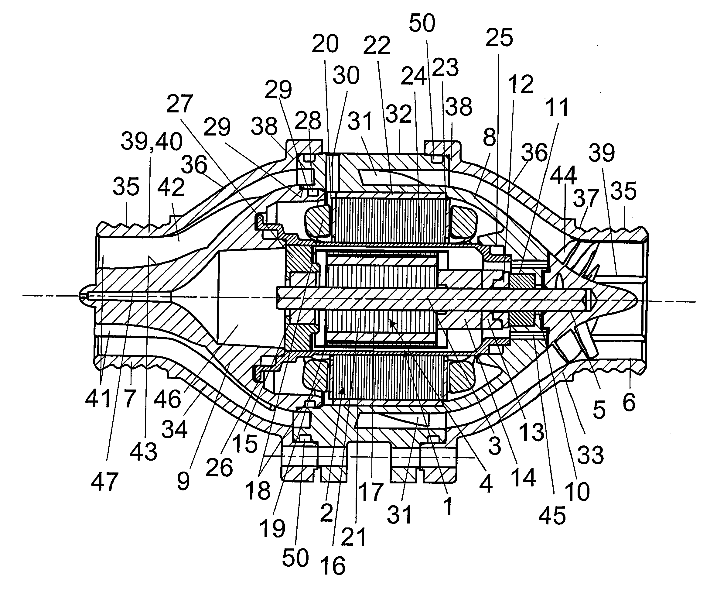
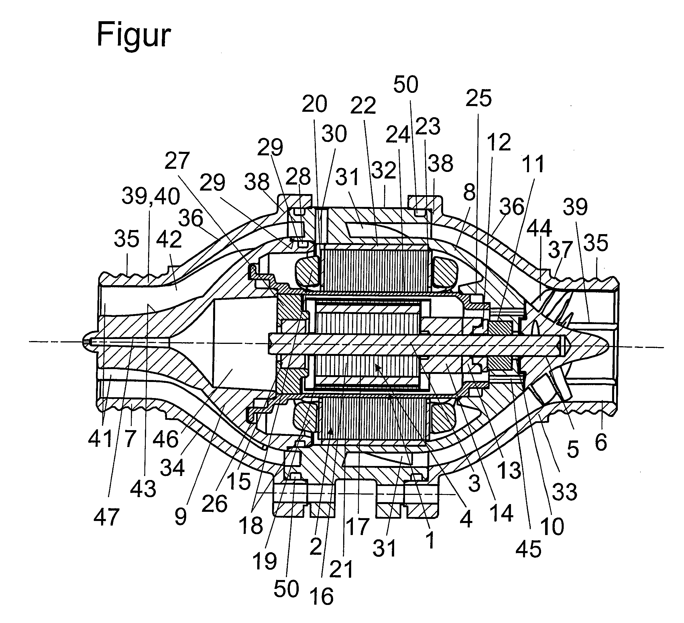
[0016]The fluid pump illustrated in the FIGURE, which is particularly suited as a coolant pump in internal combustion engines, is driven by an electronically commuted electric motor 1, formed by a stator 2 and a rotor 4 arranged on a drive shaft 3. The axial end of the drive shaft 3 is provided with an impeller 5 that is realized in a semi-axial construction and by whose rotation the fluid to be conveyed, especially a coolant, is conveyed substantially axially from an intake port 6 through the fluid pump to a pressure port 7.

[0017]The electric motor 1 is arranged in a motor housing formed by a first, suction-side motor housing part 8 and a second, pressure-side motor housing part 9. The drive shaft 3, on which the impeller 5 is arranged, is passed through the suction-side motor housing part 8. For this purpose, the suction-side motor housing part 8 has a bore 10 with a first bearing 11 being arranged therein for supporting the drive shaft 3. Behind the first bearing 11, seen from th...


PUM


Abstract

The invention relates to an electric fluid pump with a semi-axial construction, wherein the pump housing (32, 33, 34) has at least two identical pump housing parts (33, 34). This feature of the invention reduces the number of different components required to manufacture the electric fluid pump and thus reduces costs while achieving a high operating efficiency.

Description

[0001]This is a National Phase Application in the United States of International Patent Application No. PCT / EP2006 / 009762 filed Oct. 10, 2006, which claims priority on German Patent Application No. 10 2005 054 060.0, filed Nov. 10, 2005. The entire disclosures of the above patent applications are hereby incorporated by reference.FIELD OF THE INVENTION[0002]The invention is directed to a fluid pump for internal combustion engines, comprising an electric motor with a rotor arranged in a motor housing and a stator, the rotor being arranged on a drive shaft at least in a manner secured against rotation, an impeller fastened on the drive shaft, at least one set of guide vanes arranged behind the impeller in the flow direction of the fluid to be conveyed, and a pump housing enclosing the motor housing, the impeller and the guide vanes and at which a pressure port and an intake port are arranged opposite the axial ends.BACKGROUND OF THE INVENTION[0003]Fluid pumps for internal combustion en...

Claims


Application Information

Patent Timeline
Patent Type & Authority Applications(United States)
IPC IPC(8): F04B35/04
CPCF04D13/0606F04D29/588F04D29/528F04D29/426
Inventor GENSTER, ALBERT
Owner PIERBURG GMBH & CO KG NEUSS
Learn More