Multi-circuit heat exchanger

a heat exchanger and multi-circuit technology, applied in indirect heat exchangers, heat exchange apparatus safety devices, lighting and heating equipment, etc., can solve the problems of unsatisfactory refrigerant flow into the other chamber, loss of performance, loss of lubricating oil, etc., and achieve the effect of preventing fluid cross-contamination

Inactive Publication Date: 2012-01-19
CARRIER CORP
View PDF9 Cites 68 Cited by
  • Summary
  • Abstract
  • Description
  • Claims
  • Application Information

AI Technical Summary

Benefits of technology

[0008]In an aspect of the invention, a method is provided for preventing fluid cross-contamination between independent heat exchange circuits in a multi-circuit heat exchanger having a common manifold defining an interior volume having a first chamber associated with a first heat exchange circuit and a second chamber associated with a second heat exchange circuit. The method comprises the steps of: establishing a void space within the interior volume of the common manifold between the first chamber therein and the second chamber therein; and providing a vent passage between the void space and a region exterior of the common manifold.

Problems solved by technology

Flow of refrigerant from one of the first and second chambers into the other thereof is undesirable.
If refrigerant were to flow between the first and second chambers, for example through a leak in the baffle, cross-contamination of the independent refrigerant circuits would occur as refrigerant and oil passing from one refrigerant circuit into the other, which would cause a loss of performance, loss of lubricating oil and potential damage to one or both of the compressors.

Method used


Image

  • Multi-circuit heat exchanger
  • Multi-circuit heat exchanger
  • Multi-circuit heat exchanger

Examples


Embodiment Construction

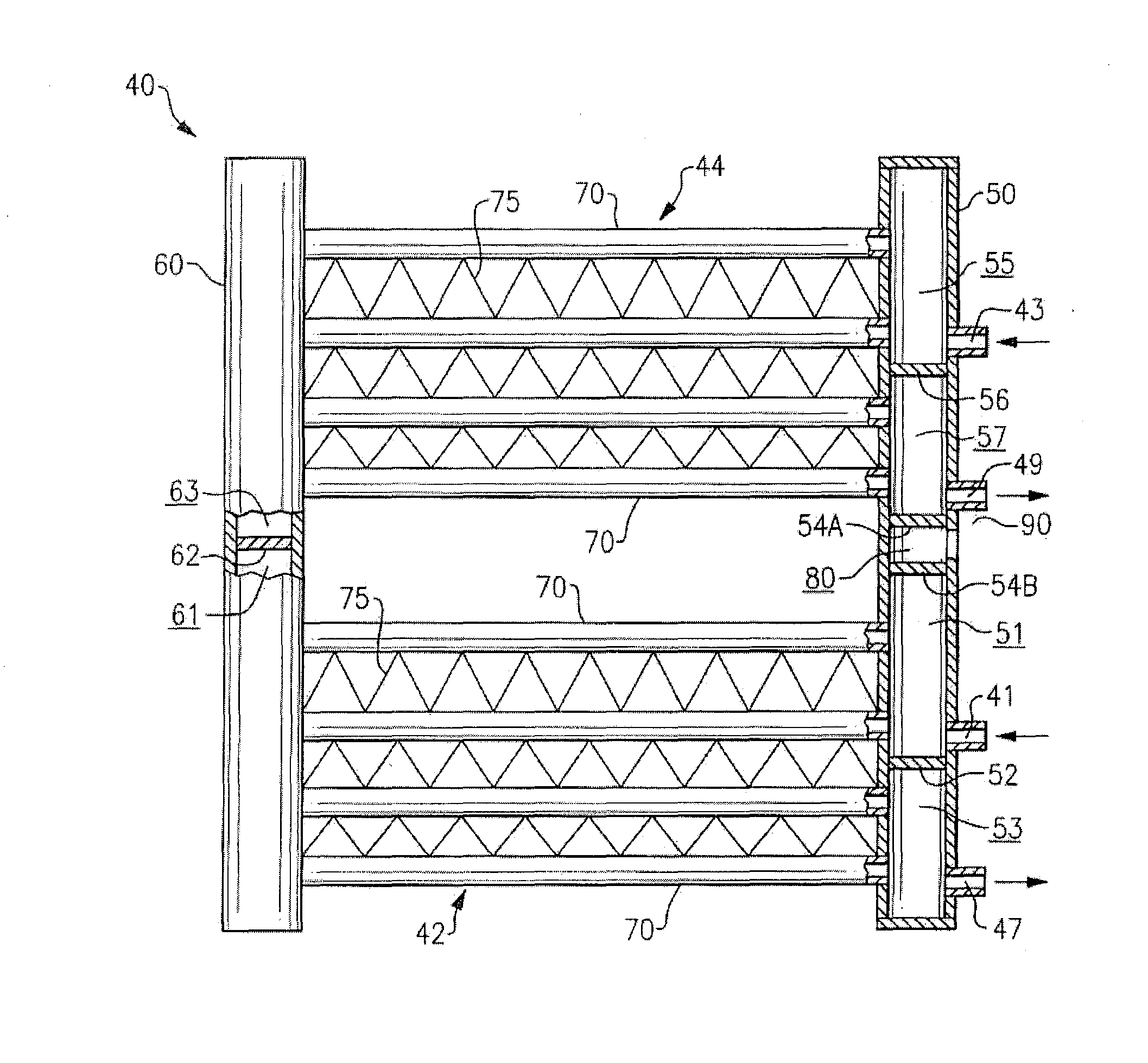
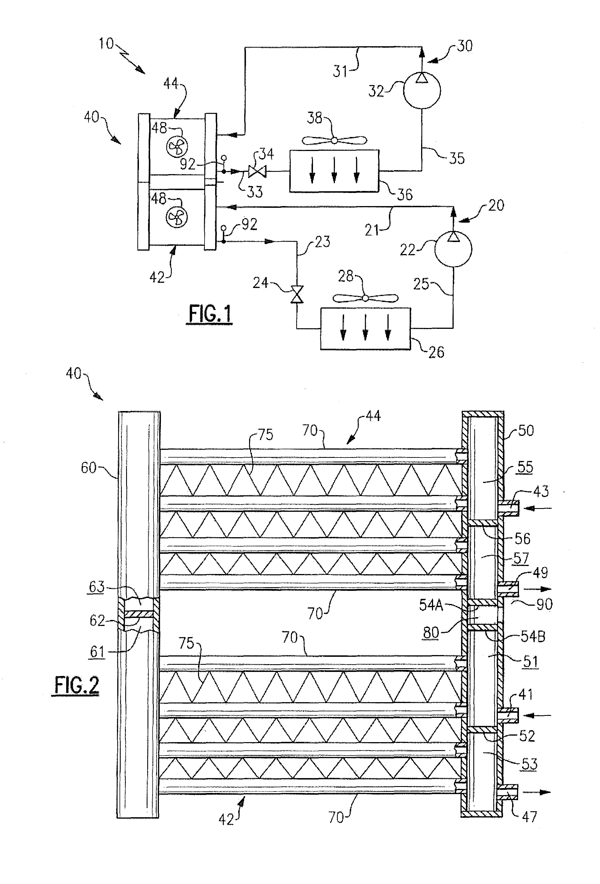
[0017]Referring initially to FIG. 1 of the drawings, there is depicted exemplary embodiments of a multiple circuit refrigerant vapor compression system 10 including two separate refrigerant circuits 20, 30, each of which operates independently of the other under the direction of a system controller (not shown) for conditioning air within separate zones of a climate-controlled space. The refrigerant vapor compression system 10 includes a dual-circuit heat exchanger 40 having a first heat exchange circuit 42 that is interdisposed in the first refrigerant circuit 20 and a second heat exchange circuit 44 that is interdisposed in the second refrigerant circuit 30. The first refrigerant circuit 20 further includes a refrigerant vapor compressor 22, an expansion device 24 and an evaporator 26 connected, together with the first heat exchange circuit 42 of the heat exchanger 40, in a closed loop refrigerant circuit by refrigerant lines 21, 23 and 25. The second refrigerant circuit 30 further...


PUM


Abstract

A baffle assembly is disposed within a manifold of a multi-circuit heat exchanger for dividing the interior volume of that manifold into a first chamber associated with one circuit and a second chamber associated with another circuit. The baffle assembly includes a pair of baffle members that extend generally transversely across the interior volume of the manifold are disposed in spaced apart relationship thereby forming a void space therebetween. The void space is in fluid communication with a region exterior of that manifold whereby any fluid leaking from either of the first or second chamber into the void space will be vented therefrom.

Description

CROSS-REFERENCE TO RELATED APPLICATION[0001]Reference is made to and this application claims priority from and the benefit of U.S. Provisional Application Ser. No. 61 / 166,433, filed Apr. 3, 2009, entitled “MULTI-CIRCUIT HEAT EXCHANGER” and U.S. Provisional Application Ser. No. 61 / 168,341, filed Apr. 10, 2009, entitled “MULTI-CIRCUIT HEAT EXCHANGER”, which applications are incorporated herein in their entirety by reference.FIELD OF THE INVENTION[0002]This invention relates generally to refrigerant vapor compression systems and, more particularly, to a parallel flow, multi-circuit tube heat exchanger for use in multiple circuit refrigerant vapor compression system, and more specifically to a parallel flow, multi-circuit tube heat exchanger adapted to prevent cross-contamination between the circuits within the heat exchanger.BACKGROUND OF THE INVENTION[0003]Refrigerant vapor compression systems are well known in the art. Air conditioners and heat pumps employing refrigerant vapor compr...

Claims


Application Information

Patent Timeline
Patent Type & Authority Applications(United States)
IPC IPC(8): F28F13/12F25B1/00F28D7/00
CPCF25B39/04F25B2400/06F28F2265/16F28D1/05391F28F9/0212F28D1/0443
Inventor KOONS, SCOTTBUSSJAGER, RUDDY C.
Owner CARRIER CORP
Why Eureka
Try Eureka