
Elevated stop indicator lights for passenger bus

Active Publication Date: 2012-01-19
KRUGH IV JOHN ADAM
View PDF6 Cites 22 Cited by
  • Summary
  • Abstract
  • Description
  • Claims
  • Application Information

AI Technical Summary

Benefits of technology

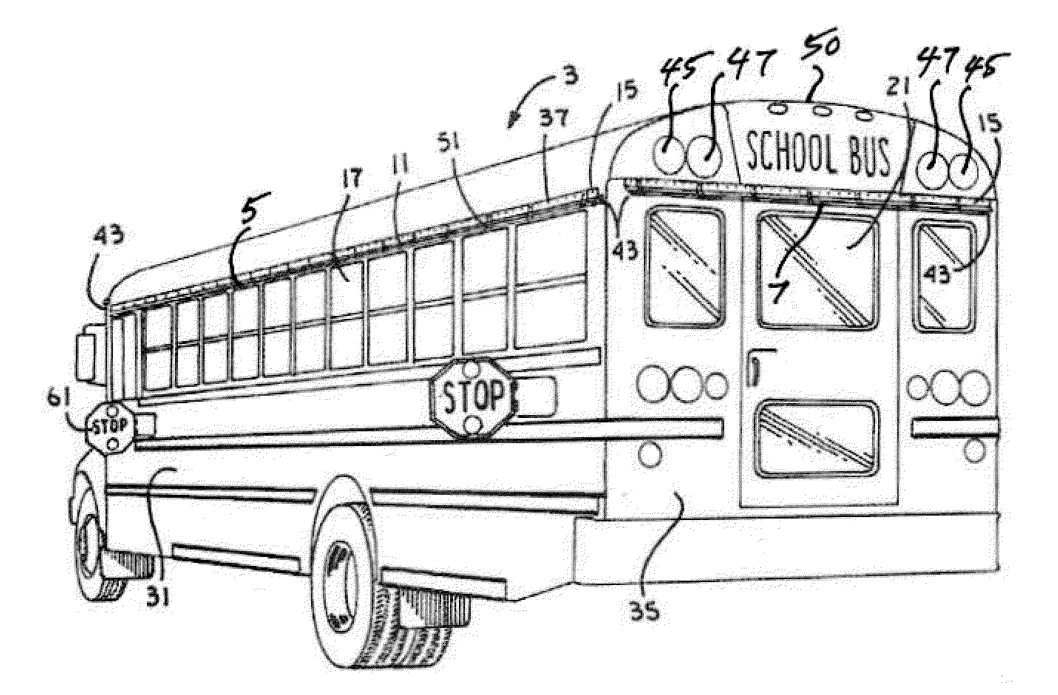
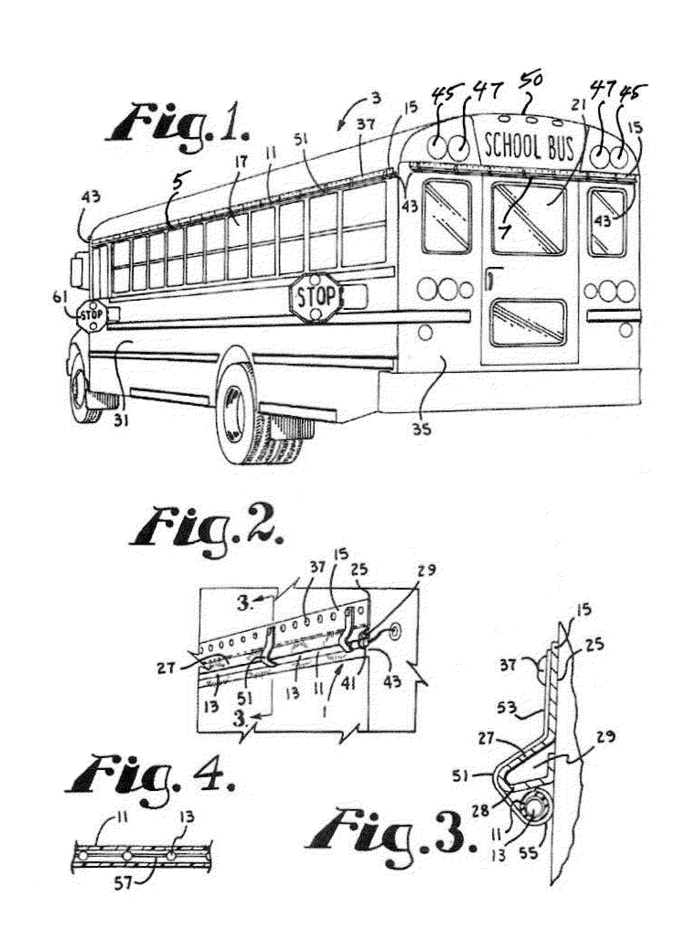
[0011]The present invention generally comprises a light strip or string of lights secured along the side of a vehicle such as a bus or delivery vehicle to function as warning lights. The lights may be secured to the gutter, drip rail or exterior sun visor extending above and along the upper periphery of the front, side and/or rear windows of a school bus or similar structure found on delivery vehicles. The lights may be positioned within a translucent, tubular housing that is preferably relatively rigid. A flexible light emitting diode (LED) strip is particularly well suited for use as the string of warning lights. The tubular housing containing the light strip may be attached to the base of the gutter, d

Problems solved by technology

Although the safety records of school buses have improved, accidents still occur when the school children exit or enter the bus.
A substantial problem is that children exiting a school bus and wanting to cross the roadway face the hazard of being struck by other vehicles traveling on the roads.
It has been found that due to the heights of many vehicles, conventional warning signs that extend from the sides of school buses are not always visible to drivers of adjacent vehicles.
Rather, due to the heights and locations of the conventional warning signs, view of the signs are often obscured by neighboring vehicles such as vans, sports utility vehicles and the like.
While the lighting strip may assist loading and unloading passengers, cars stopped alongside the bus will likely obscure the lights from other traffic.
However, neither discloses the placement of an LED strip or flexible electroluminescent light source strand mounted around the periphery of the side windows of a vehicle to elevate the warning system above neighboring traffic.
These systems are not designed to notify surrounding traffic of children loading on or unloading from the school bus.

Method used


Image

  • Elevated stop indicator lights for passenger bus
  • Elevated stop indicator lights for passenger bus
  • Elevated stop indicator lights for passenger bus

Examples


Embodiment Construction

[0023]As required, detailed embodiments of the present invention are disclosed herein; however, it is to be understood that the disclosed embodiments are merely exemplary of the invention, which may be embodied in various forms. Therefore, specific structural and functional details disclosed herein are not to be interpreted as limiting, but merely as a basis for the claims and as a representative basis for teaching one skilled in the art to variously employ the present invention in virtually any appropriately detailed structure

[0024]Certain terminology will be used in the following description for convenience in reference only and will not be limiting. For example, the words “upwardly,”“downwardly,”“rightwardly,” and “leftwardly” will refer to directions in the drawings to which reference is made. The words “inwardly” and “outwardly” will refer to directions toward and away from, respectively, the geometric center of the embodiment being described and designated parts thereof. Said ...


PUM


Abstract

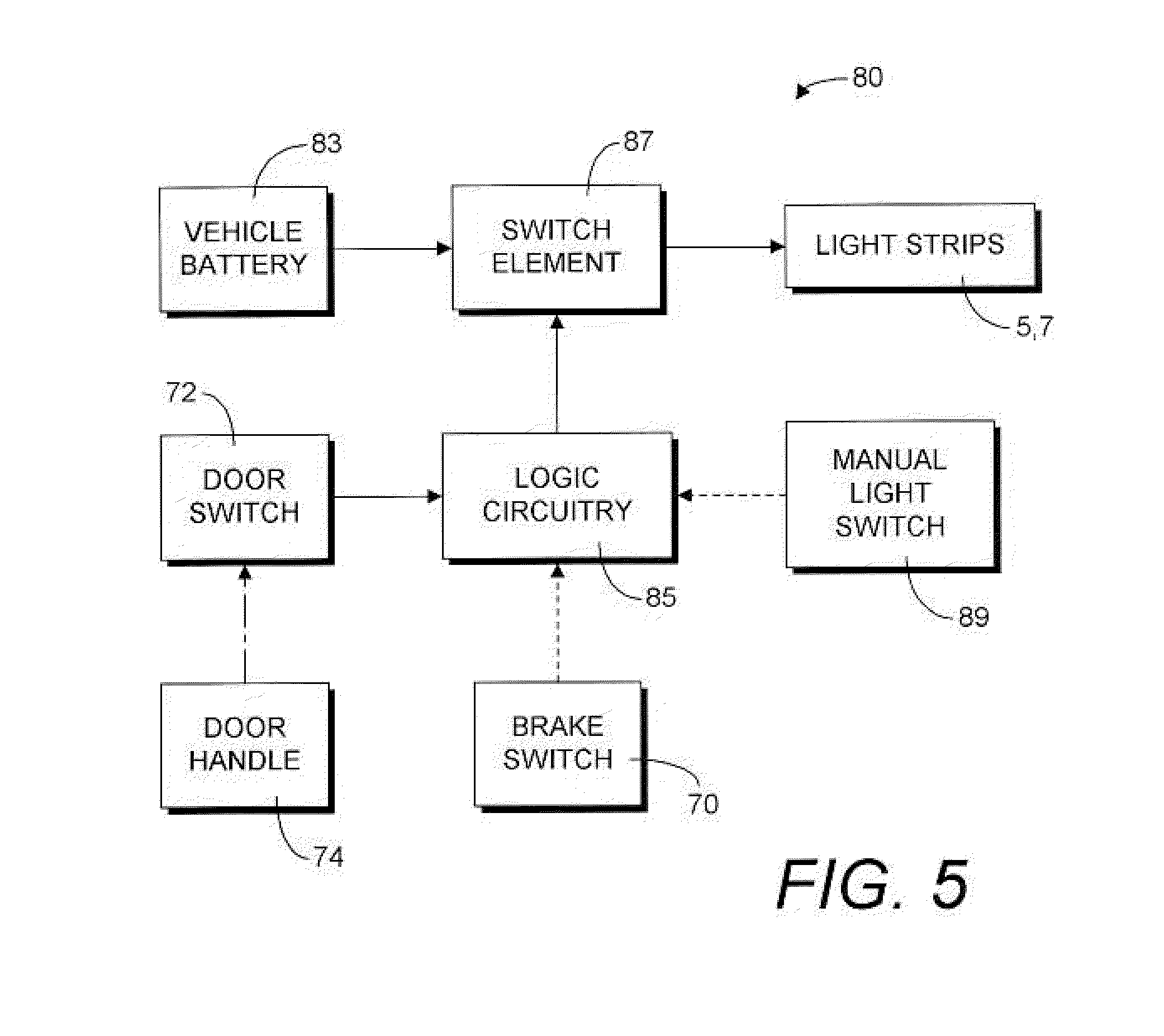
An elevated stop indicator light system for vehicles such as school buses comprises a translucent or transparent tubular housing having a strip of light emitting diodes extending therethrough, the housing being secured to a drip rail extending along and above side and / or rear windows of the vehicle by clips fastened to the vehicle. Operation of the elevated light system is coordinated with conventional warning devices, such as a fold-out stop sign and flashing red lights of the bus. The elevation of the stop indicator light system provides a highly visible warning system for surrounding traffic when the view of the conventional warning sign on the side of the bus is obscured by traffic.

Description

CROSS-REFERENCE TO RELATED APPLICATIONS[0001]This application claims the benefit of U.S. provisional patent application Ser. No. 61 / 364,252, filed Jul. 14, 2010, under 35 U.S.C.§119(e).BACKGROUND OF THE INVENTION[0002]1. Field of the Invention[0003]This invention relates to a warning system for vehicles and, in particular, to a supplemental warning light system for buses.[0004]2. Background & Description of the Related Art[0005]School buses are used extensively throughout the United States for transporting school children to and from school and school-related activities. Although the safety records of school buses have improved, accidents still occur when the school children exit or enter the bus. A substantial problem is that children exiting a school bus and wanting to cross the roadway face the hazard of being struck by other vehicles traveling on the roads. Regulations in most areas of the United States, Canada, and other countries require school buses to activate flashing yello...

Claims


Application Information

Patent Timeline
IPC IPC(8): B60Q1/26
CPCB60Q1/50B60Q1/32B60Q1/543
Inventor KRUGH, IV, JOHN ADAM
Owner KRUGH IV JOHN ADAM
Learn More