Waveguide-type optical circuit

Active Publication Date: 2012-01-19
FURUKAWA ELECTRIC CO LTD
View PDF6 Cites 7 Cited by
  • Summary
  • Abstract
  • Description
  • Claims
  • Application Information

AI Technical Summary

Benefits of technology

[0006]In accordance with one aspect of the present invention, a waveguide-type optical circuit comprises an optical coupler being an optical branch coupler constructed from waveguide cores whic

Problems solved by technology

However, there is a problem in that large PDL prevents the PLC-type optical coupler

Method used


Image

  • Waveguide-type optical circuit
  • Waveguide-type optical circuit
  • Waveguide-type optical circuit

Examples


first embodiment

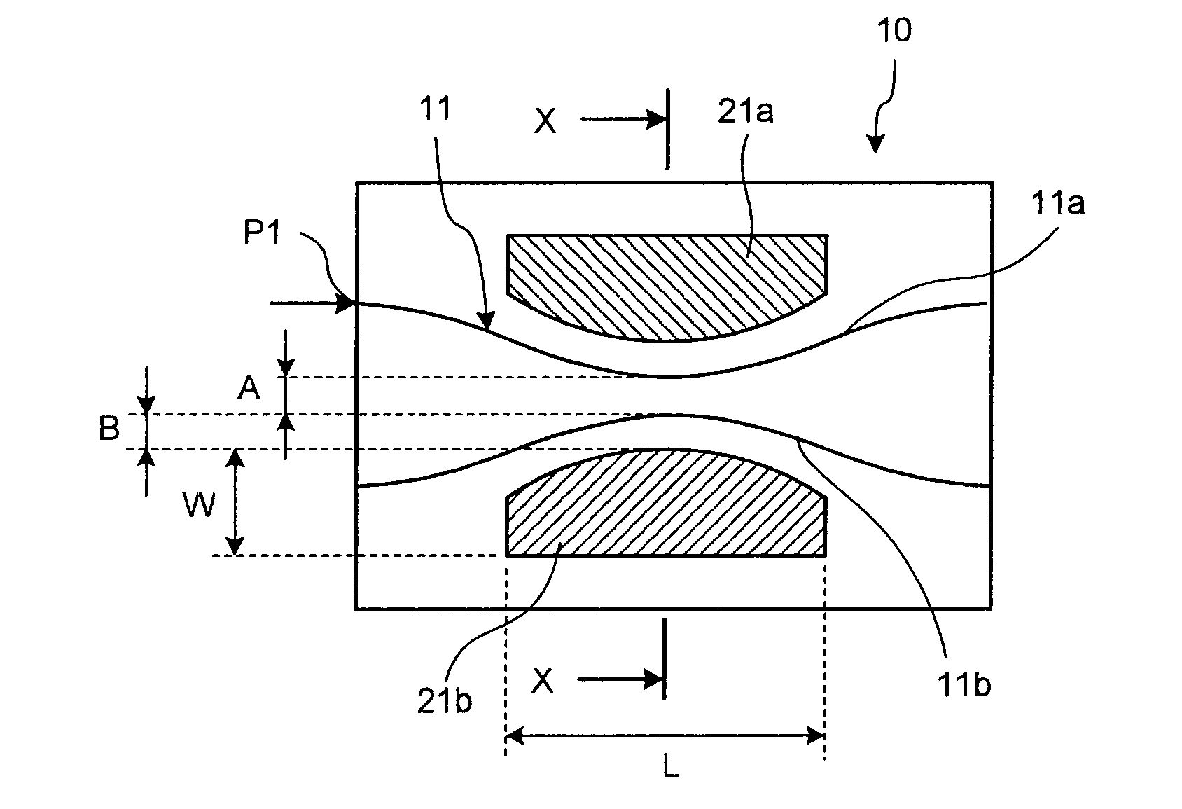
[0021]A schematic configuration of a waveguide-type optical circuit according to a first embodiment of the present invention will be explained below with reference to FIG. 1 to FIG. 3.

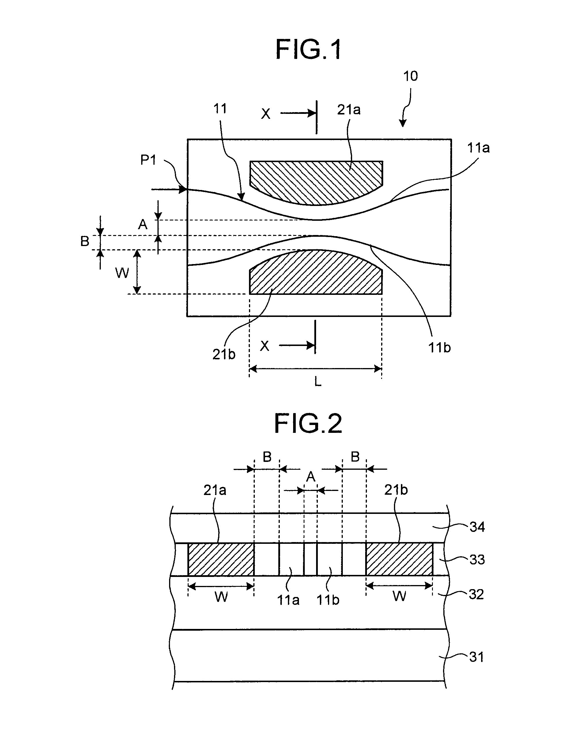
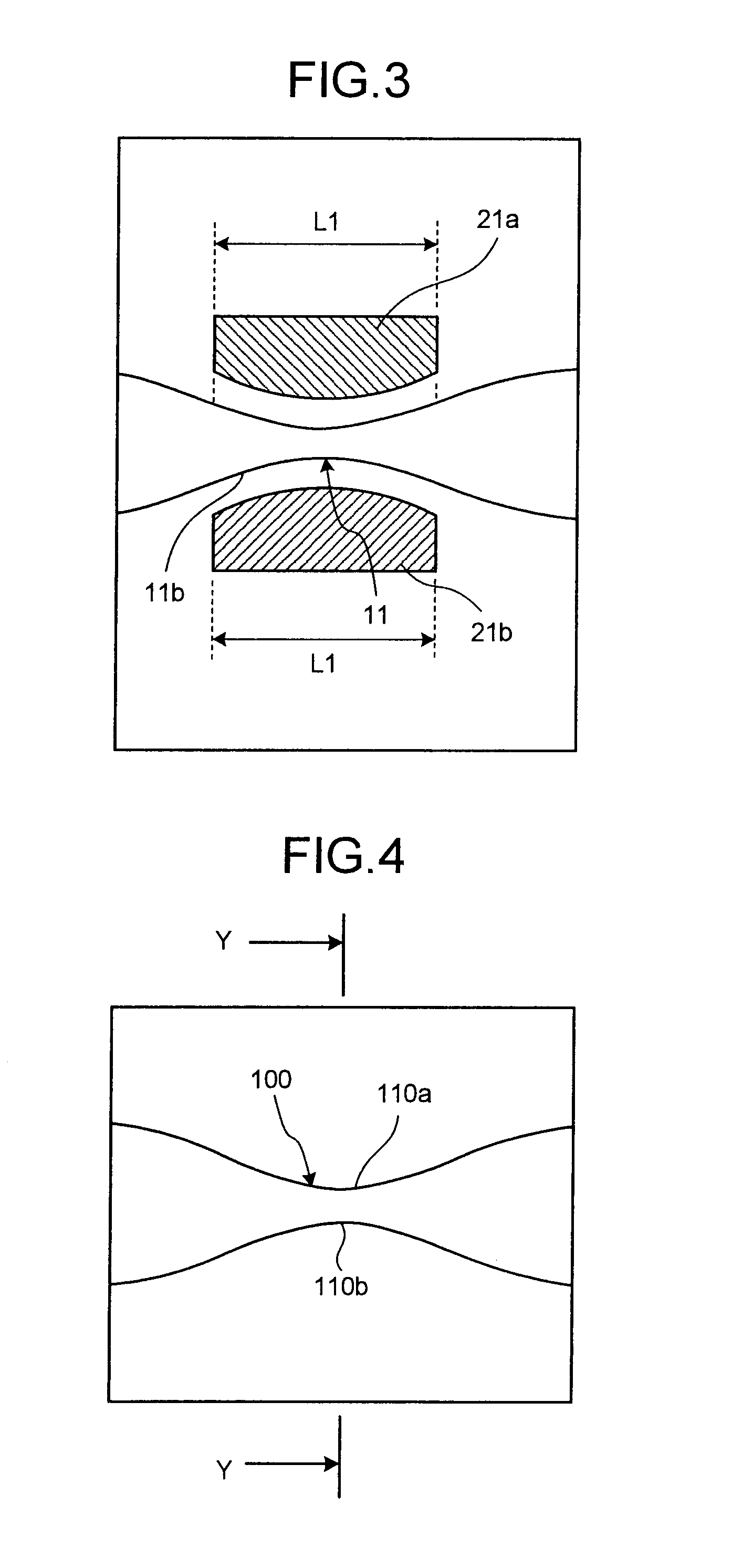
[0022]FIG. 1 represents a schematic configuration of the waveguide-type optical circuit according to the first embodiment of the present invention, FIG. 2 is a cross-sectional view taken along line X-X in FIG. 1, and FIG. 3 is a diagram for explaining a length of a dummy pattern in FIG. 1.

[0023]A waveguide-type optical circuit 10 according to the first embodiment shown in FIG. 1 includes one directional coupler 11. The directional coupler 11 is an optical coupler (optical branch coupler) configured so that waveguide cores 11a and 11b are arranged closely facing to each other. Dummy patterns 21a and 21b are formed along both sides of the waveguide cores 11a and 11b so as to prevent optical major axes of the waveguide cores 11a and 11b from including. More specifically, the dummy patterns 21a and 21b are...

second embodiment

[0056]FIG. 7 represents a schematic configuration of a waveguide-type optical circuit 10A according to a second embodiment of the present invention.

[0057]The waveguide-type optical circuit according to the second embodiment shown in FIG. 7 is configured as a PLC-type variable optical attenuator (PLC-VOA) 10A.

[0058]The PLC-VOA 10A is provided with a Mach-Zehnder Interferometer (MZI) circuit 20 that includes two directional couplers 11 and 12, two arm waveguides 13 and 14 connected between the two directional couplers 11 and 12 respectively, and a thin film heater 15 disposed on the arm waveguide 14. Here, although the PLC-VOA configured as having one MZI circuit will be explained, the present invention is also applicable to PLC-VOA connected to multiple-stage MZI circuits for the present invention is to be applied to an optical coupler in the MZI circuit.

[0059]In the PLC-VOA 10A, the power is externally applied to the thin film heater 15 to heat the arm waveguide 14 so that an effect...


PUM


Abstract

A waveguide-type optical circuit comprises an optical coupler being an optical branch coupler constructed from waveguide cores which are closely arranged each other, and dummy patterns that lay along sides of the waveguide cores in the optical coupler for preventing optical major axes of the waveguide cores from inclining.

Description

BACKGROUND OF THE INVENTION[0001]1. Field of the Invention[0002]The present invention relates to a waveguide-type optical circuit provided with an optical coupler such as a directional coupler.[0003]2. Description of the Related Art[0004]In a conventional Directional Coupler (DC), as described in Paragraph 0024 in International Publication Pamphlet No. WO 2006 / 075702, a region (gap portion) sandwiched between two waveguide cores at a close portion of waveguides is supplied with a less amount of glass particles during formation of upper cladding because waveguide patterns are close to each other, and the density of the glass particles therefore becomes sparse. Meanwhile, a region (non-gap portion) that is not sandwiched between the two waveguide cores is sufficiently supplied with the glass particles. Therefore, the densities of the glass particles in the gap portion and the non-gap portion become different from each other. After the upper cladding is formed, stresses to incline the ...

Claims


Application Information

Patent Timeline
IPC IPC(8): G02B6/125G02F1/035
CPCG02B6/122G02B6/125G02F1/225G02B2006/12159G02F1/0147G02B6/126
Inventor MATSUBARA, NORITAKANARA, KAZUTAKA
Owner FURUKAWA ELECTRIC CO LTD
Why Eureka
Try Eureka