
Cable connection device, line feedthrough provided therewith, and use thereof

a connection device and line feedthrough technology, applied in the direction of coupling device connection, coupling device details, aperture leaage reduction, etc., can solve the problems of optical connectors, optical lines and electronics to be shielded, and the interface between optical lines and electronics to be protected, etc., to achieve simple design

Inactive Publication Date: 2012-01-19
AIRBUS OPERATIONS GMBH
View PDF6 Cites 19 Cited by
  • Summary
  • Abstract
  • Description
  • Claims
  • Application Information

AI Technical Summary

Benefits of technology

[0012]In comparison with the prior art, the object of the invention is to design a cable connection device in such a way that it can be used universally with a relatively simple design and provides electromagnetic shielding which is as improved as possible.
[0019]By virtue of this amazingly simple design, it is possible to produce a universal cable connection device, with which both optical cables and electrical cables can be connected to a housing that is to be electromagnetically shielded in the region of a cable feedthrough opening in the housing in electrically shielding fashion.
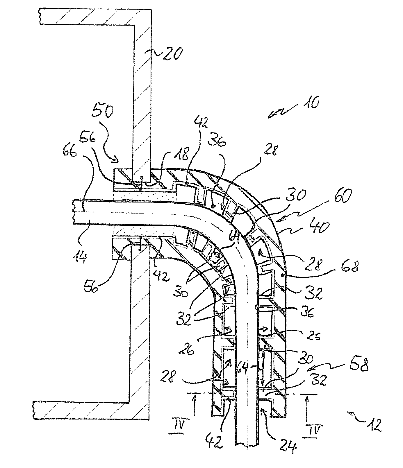
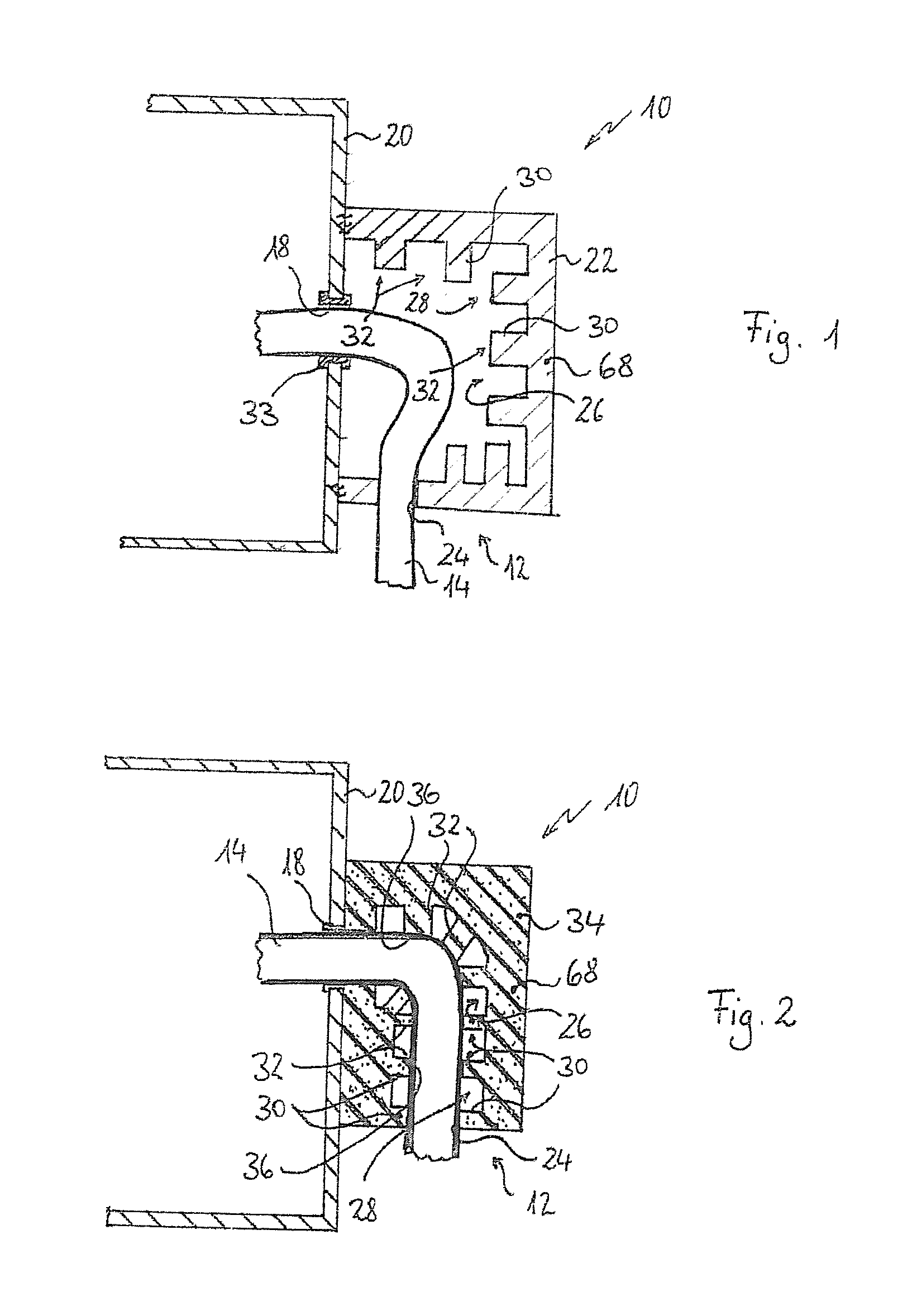
[0021]Covering of the cable feedthrough opening is preferably achieved in such a way that the sheath guides the cable on a bent-back or curved path. The cable is therefore guided on a curved or bent-back path between an end region of the sheath, said end region being associated with the cable feedthrough opening in the housing, and a cable inlet, where the cable enters the sheath from the outside. There is therefore no linear feedthrough through the sheath, with the result that electromagnetic radiation which should enter the sheath would need to be deflected at least once in order to be able to pass through the sheath. Such radiation is weakened by the shielding structures, however, with the result that perfect shielding is possible.
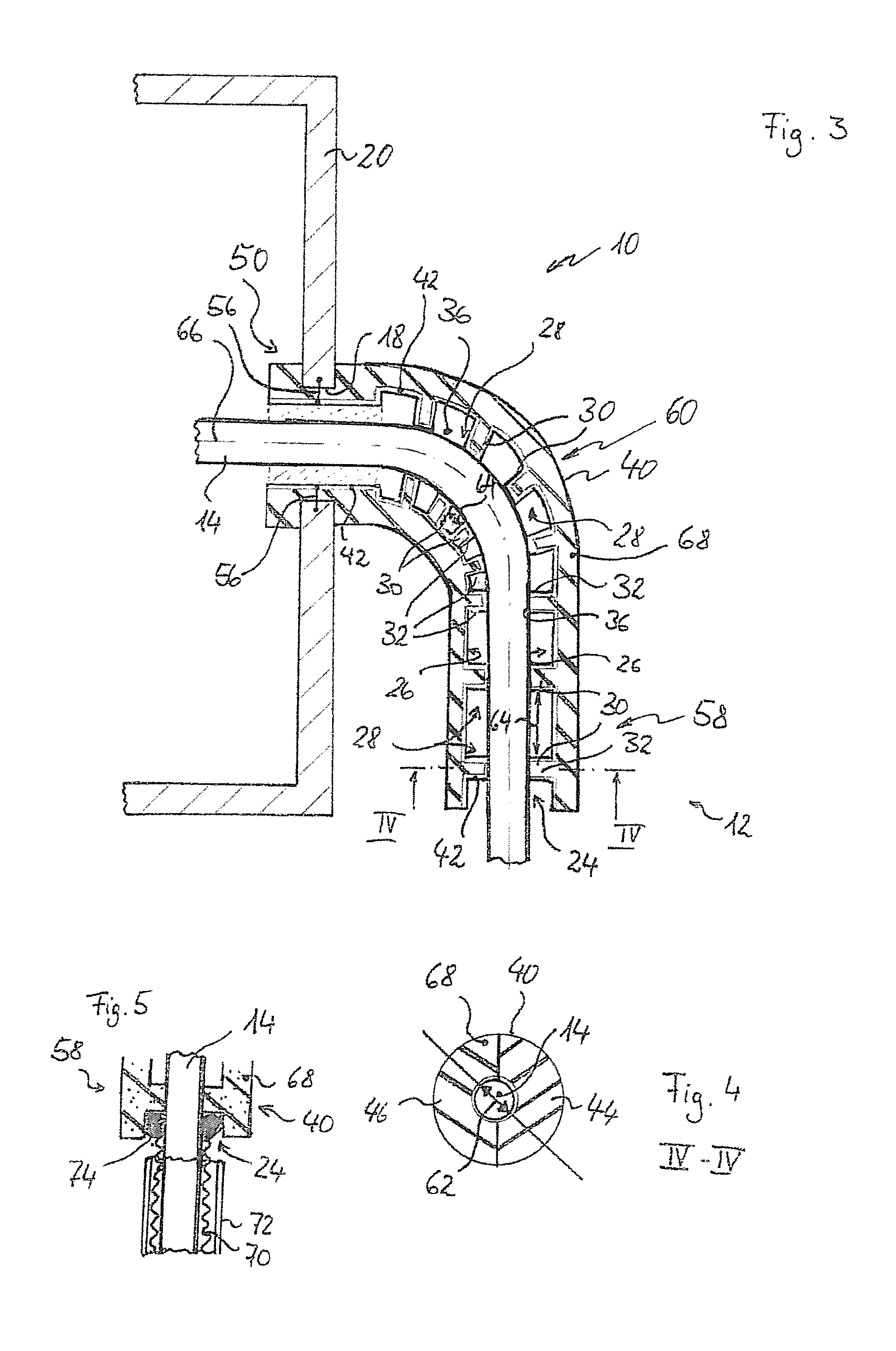
[0025]The baffles or ribs can follow on from one another at regular intervals, in a similar way to as is already known in optical baffles in optical devices. However, irregular intervals are also possible and possibly even advantageous. The use of irregular intervals makes it possible to avoid possible resonances, for example. By way of example, the intervals for the baffles or ribs are designed to be greater in the region of an inlet of the cable connection device and smaller in the region of a curvature or bent-back portion.

Problems solved by technology

In fact, the optical fibers do not need to be shielded in the region of their external run, but the interface between the optical lines and electronics to be shielded represents a problem.
In particular, the optical connector represents a problem.

Method used


Image

  • Cable connection device, line feedthrough provided therewith, and use thereof
  • Cable connection device, line feedthrough provided therewith, and use thereof
  • Cable connection device, line feedthrough provided therewith, and use thereof

Examples


Embodiment Construction

[0035]The figures illustrate different embodiments of a cable connection device with the overall designation 10, wherein the same reference numerals are used for identical or corresponding parts. The cable connection device 10 is used for forming a line feedthrough 12, in which an optical or electrical cable 14 is passed through a cable feedthrough opening 18 in a metal housing 20.

[0036]The metal housing 20 serves to accommodate electronics (not illustrated), which are intended to be shielded with respect to electromagnetic radiation from the outside or with respect to the emission of electromagnetic radiation from the electronics. Therefore, said electronics are accommodated in the electrically conductive metal housing 20. However, electromagnetic radiation could pass through the cable feedthrough opening 18.

[0037]Cables 14, which pass out of an electromagnetically sealed metal housing 20 can have the effect that electromagnetic radiation can enter the metal housing 20. This can oc...


PUM


Abstract

The invention relates to a cable connection device for connecting a cable to a housing that is to be electromagnetically shielded, comprising a sheath, which serves to surround the cable in the region of a cable feedthrough opening in the housing and is designed to be electrically conductive at least at its surface. In order to achieve a cable connection device with a simple design which can be used for different cables and has improved shielding, the invention proposes that the sheath completely covers a cable feedthrough opening, which is associated with the housing, when viewed in a direction axial to the cable feedthrough opening, the sheath being provided with shielding structures for damping electromagnetic radiation on an inner surface, which points towards the cable to be accommodated.

Description

CROSS-REFERENCE TO RELATED APPLICATIONS[0001]This application is a continuation of PCT / EP2010 / 051684 filed Feb. 11, 2010 and claims the benefit of and priority to German Patent Application No. 10 2009 008 506.8, filed Feb. 12, 2009, the entire disclosures of which are herein incorporated by reference.FIELD OF THE INVENTION[0002]The invention relates to a cable connection device for connecting a cable to a housing that is to be shielded electrically in accordance with the preamble of patent claim 1, as is disclosed in DE 198 38 951 C1, for example. Hereafter, more detailed reference is made to said document. In addition, the invention relates to a line feedthrough provided with such a cable connection device for feeding an optical or electrical line through a feedthrough opening in a housing that is to be electromagnetically shielded, such as in particular a metal housing. Finally, the invention relates to a use for such a cable connection device.[0003]It is often desirable or necess...

Claims


Application Information

Patent Timeline
Patent Type & Authority Applications(United States)
IPC IPC(8): H01R9/03H01R13/648
CPCH05K9/0018H02G3/22
Inventor DEIMEL, PETERBROWNJOHN, NICHOLAS E.
Owner AIRBUS OPERATIONS GMBH
Learn More