Supercharge Your Innovation With Domain-Expert AI Agents!

Inertia free drive for cryogenic piston expander

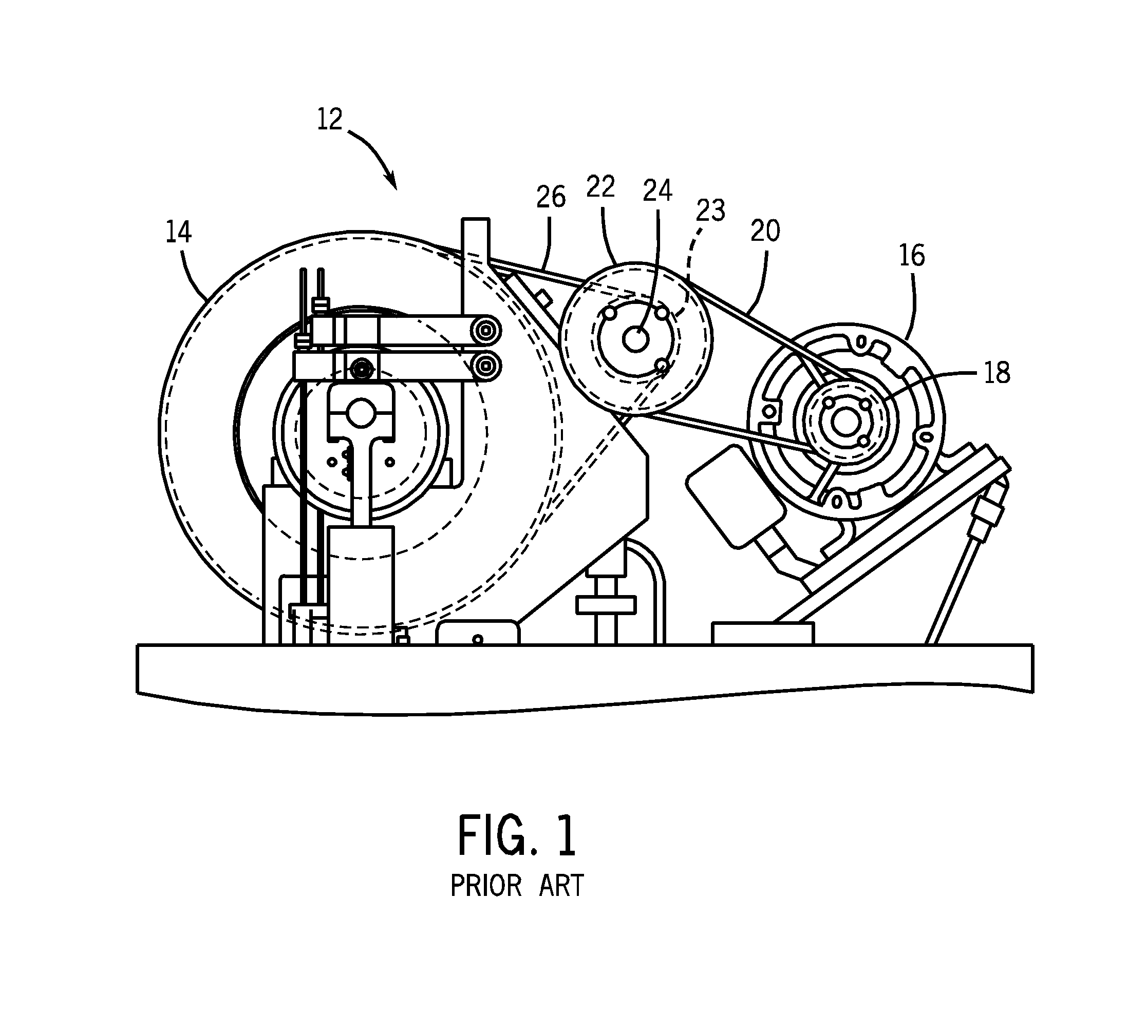
a cryogenic piston and expander technology, applied in the direction of reciprocating piston engines, machines/engines, positive displacement engines, etc., can solve the problems of belt dusting, frequent maintenance, and large amount of inertia of conventional cryogenic piston expanders

Inactive Publication Date: 2012-01-26
KOZYRCZAK MAKSYMILIAN
View PDF1 Cites 0 Cited by
  • Summary
  • Abstract
  • Description
  • Claims
  • Application Information

AI Technical Summary

Benefits of technology

[0007]In one aspect of the present invention, a cryogenic piston expander comprises a motor adapted to drive a motor shaft; a first sprocket attached to the motor shaft; a second sprocket

Problems solved by technology

Conventional cryogenic piston expanders require a large amount of inertia, typically due to the rotation of a large flywheel.
This large amount of inertia may increase the load on the variable frequency drive (VFD) motor, cause belt dusting and may require frequent maintenance.

Method used


Image

  • Inertia free drive for cryogenic piston expander
  • Inertia free drive for cryogenic piston expander
  • Inertia free drive for cryogenic piston expander

Examples


Embodiment Construction

[0012]The following detailed description is of the best currently contemplated modes of carrying out exemplary embodiments of the invention. The description is not to be taken in a limiting sense, but is made merely for the purpose of illustrating the general principles of the invention, since the scope of the invention is best defined by the appended claims.

[0013]Various inventive features are described below that can each be used independently of one another or in combination with other features.

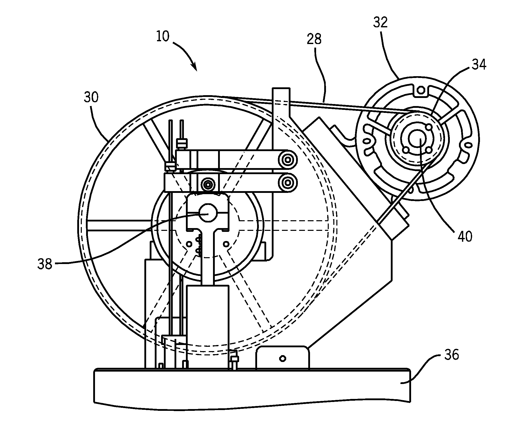
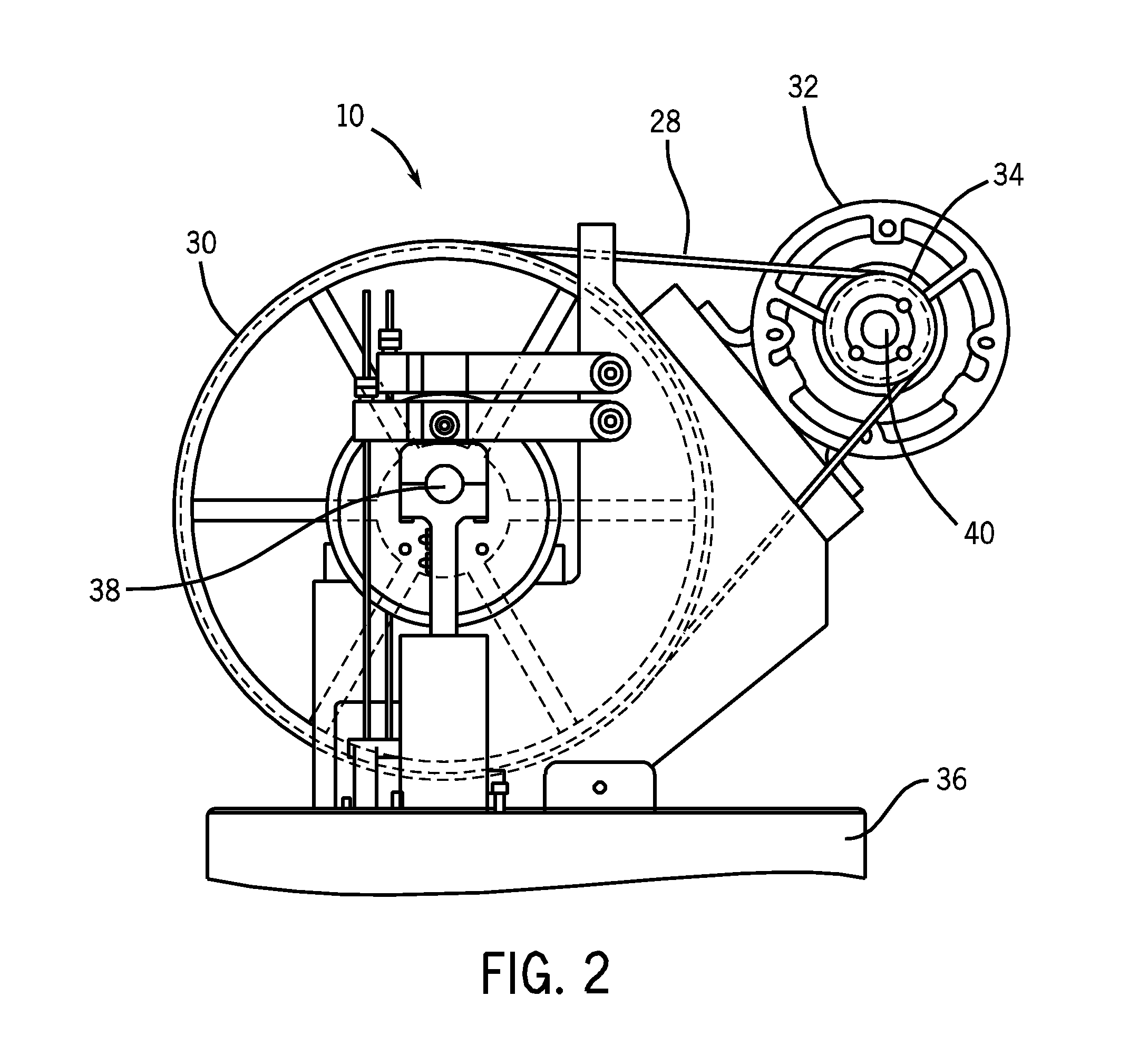
[0014]Broadly, an embodiment of the present invention provides a cryogenic piston expander may reduce or eliminate the inertia of the system, as compared to conventional cryogenic piston expanders. The cryogenic piston expander of the present invention may use a single bent running from a motor to a large sprocket mounted on a main shaft of the cryogenic piston expander.

[0015]Referring to FIG. 2, a cryogenic piston expander 10 may include a motor 32 mounted off a base plate 36 of the cryog...


PUM


Abstract

A cryogenic piston expander may reduce or eliminate the inertia of system, as compared to conventional cryogenic piston expanders that utilize a heavy flywheel. The cryogenic piston expander of the present invention may use a single bent running from a motor to a large sprocket mounted on a main shaft of the cryogenic piston expander.

Description

CROSS-REFERENCE TO RELATED APPLICATIONS[0001]This application claims the benefit of priority of U.S. provisional patent application No. 61 / 366,622, filed Jul. 22, 2010, the contents of which are herein incorporated by reference.BACKGROUND OF THE INVENTION[0002]The present invention relates to cryogenic piston expanders and, more particularly, to an inertia free drive for a cryogenic piston expander.[0003]Systems operating at cryogenic temperatures generally have a cryogenic refrigeration unit attached to the system to minimize or eliminate boil-off of the cryogenic coolant. A cryogenic refrigeration unit including an expansion device, compressor, and heat exchanger is known. High pressure fluid from the compressor is passed through the heat exchanger and introduced into the expansion device, such as a cryogenic piston expander. Expansion of the fluid in the expansion device reduces the temperature and pressure of the fluid. Heat energy is transferred from the expanding fluid by the ...

Claims


Application Information

Patent Timeline
IPC IPC(8): F01B9/00
CPCF01B9/00
Inventor KOZYRCZAK, MAKSYMILIAN
Owner KOZYRCZAK MAKSYMILIAN
Features
  • R&D
  • Intellectual Property
  • Life Sciences
  • Materials
  • Tech Scout
  • Unparalleled Data Quality
  • Higher Quality Content
  • 60% Fewer Hallucinations
Learn More