Sound-Velocity Dewatering System

a sound velocity and dewatering technology, applied in the direction of separation process, instruments, borehole/well accessories, etc., can solve the problems of large manpower, prevent the operators from focusing on more important issues, and build-up of water level in hydrocarbon storage tanks

Active Publication Date: 2012-01-26
SAUDI ARABIAN OIL CO
View PDF15 Cites 9 Cited by
  • Summary
  • Abstract
  • Description
  • Claims
  • Application Information

AI Technical Summary

Benefits of technology

The present invention relates to methods for controlling the level of hydrocracked products (hydrocarbons) released from industrial equipment such as refineries or chemical plants. More specifically, this patent describes a way to measure the speed at which these products are moving through pipes and use that data to control the operation of a valve that regulates their release. By doing this, it becomes possible to better manage the production process and minimize the loss of valuable materials during processing.

Problems solved by technology

The technical problem addressed in this patent text relates to finding a way to automatically remove excess water levels from hydrocracking tanks without requiring significant modification to the system, while also being affordable and reliable. Existing solutions like automated pumps or vacuum systems come with their own set of challenges including high costs, difficulty in implementation, and potential safety risks. Therefore, there is a need for a new approach that overcomes these limitations.

Method used


Image

  • Sound-Velocity Dewatering System
  • Sound-Velocity Dewatering System
  • Sound-Velocity Dewatering System

Examples


Embodiment Construction

[0020]While the invention will be described in connection with several embodiments, it will be understood that it is not intended to limit the invention to those embodiments. On the contrary, it is intended to cover all the alternatives, modifications and equivalence as may be included within the spirit and scope of the invention defined by the appended claims.

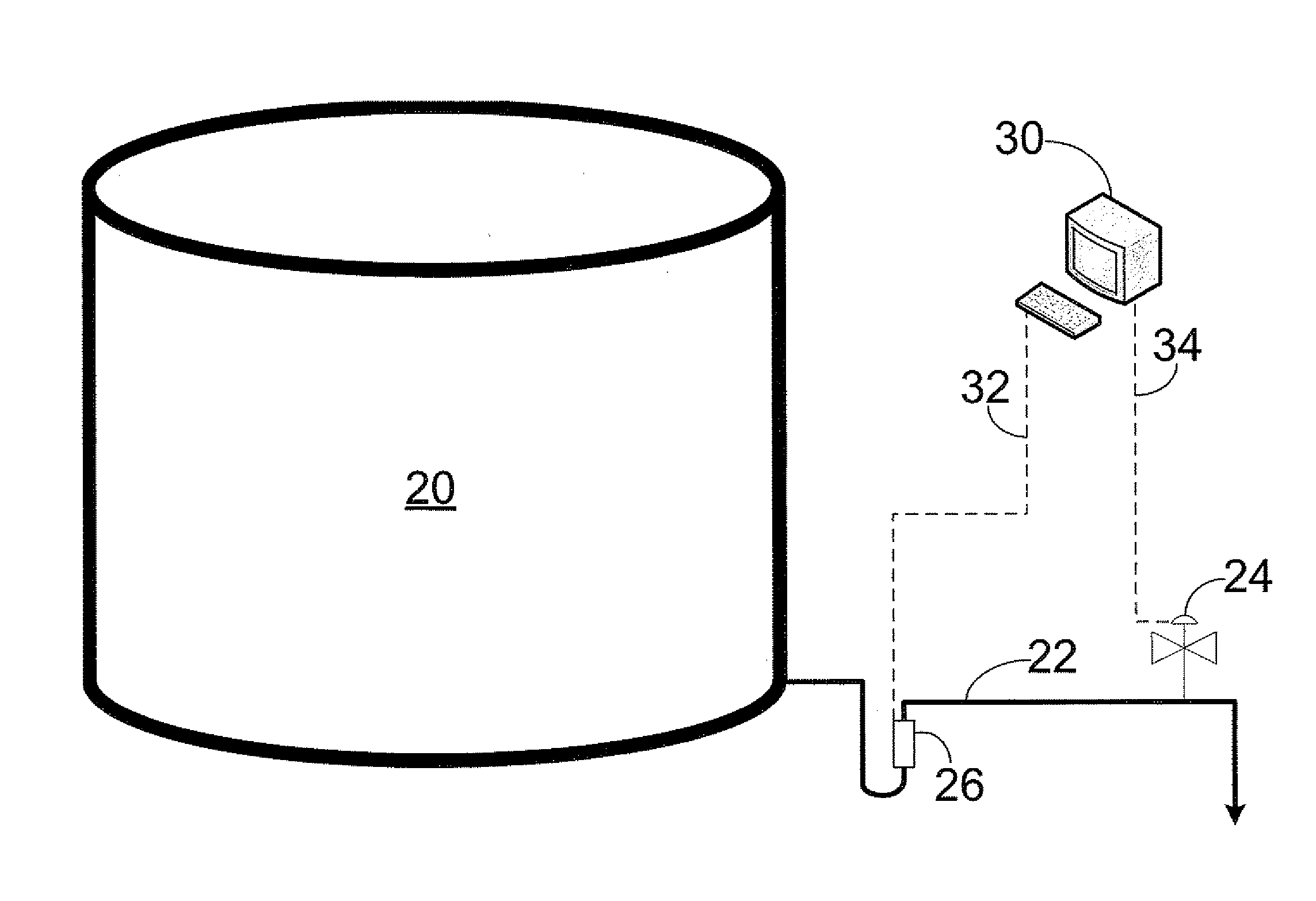
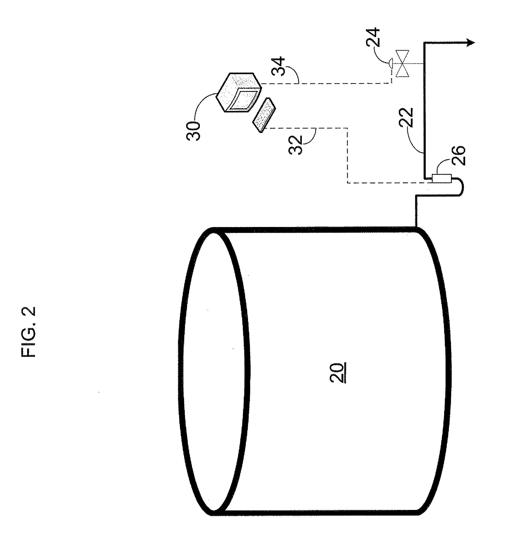
[0021]One embodiment of the invention provides for an apparatus for controlling hydrocarbon content in the water stream exiting the dewatering the tank. The apparatus can include the sound velocity detector, a control system, and a control element. Preferably, the sound velocity detector includes transducers, an transmitter, and an optional temperature probe. The control system can be a distributed control system (DCS), a terminal monitoring system (TMS), a programmable logic controller (PLC), or any other similar customizable control system. The control system can be either mounted in the field or in a control room. Examples ...


PUM


Abstract

A method and apparatus for an improved dewatering tank system that allows for safely controlling a water stream exiting the dewatering tank system. The apparatus can include a sound velocity detector, a control system, and a control element. The sound velocity detector can include a transducer, a detector, and a transmitter. The control system can include a computer and a program product. The apparatus can optionally include a dewatering tank, a drain line, and a controllable valve. The apparatus allows for transmitting sound energy through the water stream flowing in the drain lined that is connected to the dewatering tank, calculating the velocity of the sound energy as the sound energy travels through the water stream, monitoring the velocity of the sound energy for a period of time, and controlling the position of the controllable valve depending on the calculated velocity of the sound energy.

Description


Claims


Application Information

Patent Timeline
Owner SAUDI ARABIAN OIL CO
Why Eureka
Try Eureka