System and method for multiple mode flexible excitation in sonic infrared imaging

a technology of infrared imaging and excitation, applied in the direction of optical radiation measurement, instruments, specific gravity measurement, etc., can solve the problems of high inspection intensity, low efficiency, and loss of structural integrity, and achieve the effect of reducing the number of inspectors

Inactive Publication Date: 2005-08-04
SIEMENS ENERGY INC
View PDF30 Cites 38 Cited by
  • Summary
  • Abstract
  • Description
  • Claims
  • Application Information

AI Technical Summary

Benefits of technology

[0013] In one embodiment, the sound signal includes a combination of frequencies selected for the particular structure so that the frequency occurs or doesn't occur at or near an eigen-mode of the structure. In this embodiment, the sound source can generate a combination of signals centered at different frequencies, a chirp-signal, a pulse-envelope signal, etc., to vary the sound signal in frequency, amplitude and duration so that the eigen-mode is excited or avoided for flexible multiple mode excitation.

Problems solved by technology

Loss of structural integrity is typically caused by material defects, such as cracks, delaminations, disbonds, corrosion, inclusions, voids, etc., that may exist in the structure.
But, it is known that cracks or defects that may affect the integrity of structural components may not be readily visible without the use of special techniques to aid the examiner.
This technique has the disadvantage, however, that it is highly inspector intensive and dependent because the person inspecting for the fluorescence must be skilled.
This technique has the drawback, however, that it is also very operator intensive, and is also extremely slow and tedious.
Although this technique has been successful for detecting disbonds and corrosions, it is ordinarily not successful for detecting vertical cracks in the component, that is, those cracks that are perpendicular to the surface of the component.
This is because a fatigue crack looks like a knife edge to the planar heat pulse, and therefore no, or minimal, heat reflections occur from the crack making it difficult or impossible to see in a thermal image.
The ultrasonic waves cause the opposing edges of the crack to rub together causing the crack to heat up.

Method used


Image

  • System and method for multiple mode flexible excitation in sonic infrared imaging
  • System and method for multiple mode flexible excitation in sonic infrared imaging
  • System and method for multiple mode flexible excitation in sonic infrared imaging

Examples


Embodiment Construction

[0034] The following description of the embodiments of the invention directed to a defect detection system for detecting defects in a structure is merely exemplary in nature, and is in no way intended to limit the invention or its applications or uses.

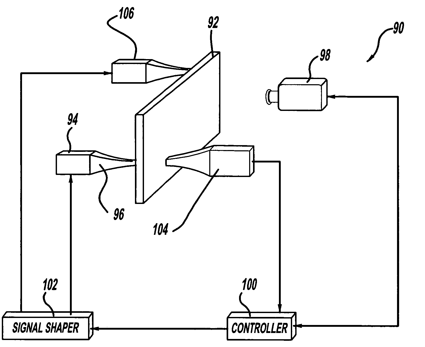
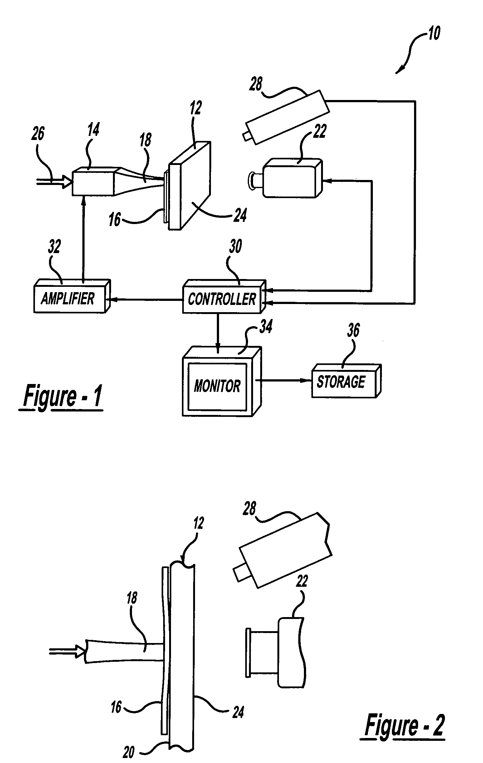
[0035]FIG. 1 is a block diagram of a defect detection system 10, according to an embodiment of the present invention. The system 10 is being used to detect defects, such as cracks, corrosion, delaminations, disbonds, etc., in a component 12. The component 12 is intended to represent any structural component or material, such as an aircraft skin, turbine blade, turbine rotor, power generator, vehicle cylinder head, etc., that may include these types of defects that could cause catastrophic failure. It is stressed that the component 12 does not need to be metal, but can be other materials, such as ceramics, composites, etc.

[0036] The system 10 includes an ultrasonic transducer 14 that generates a sound signal within a certain ultrasoni...


PUM

PropertyMeasurementUnit
frequencyaaaaaaaaaa
frequencyaaaaaaaaaa
frequencyaaaaaaaaaa

Abstract

A defect detection system for thermally imaging a structure that has been energized by a sound energy. The system includes a transducer that couples a sound signal into the structure, where the sound signal causes defects in the structure to heat up. In one embodiment, the sound signal has one or more frequencies that are at or near an eigen-mode of the structure.

Description

CROSS-REFERENCE TO RELATED APPLICATIONS [0001] This is a Continuation application of U.S. patent application Ser. No. 10 / 647,569, titled System and Method for Multiple Mode Flexible Excitation and Acoustic Chaos in Sonic Infrared Imaging, filed Aug. 25, 2003, which claims the benefit of U.S. Provisional Application No. 60 / 453,431, titled System and Method for Acoustic Chaos and Sonic Infrared Imaging, filed Mar. 10, 2003 and U.S. Provisional Application No. 60 / 407,207, titled System and Method for Acoustic Chaos and Sonic Infrared Imaging, filed Aug. 28, 2002.BACKGROUND OF THE INVENTION [0002] 1. Field of the Invention [0003] This invention relates generally to a system and associated method for detecting defects in a material and, more particularly, to a system and associated method for detecting defects in a material, where the system includes a transducer for coupling a multiple mode flexible excitation signal into the material, and includes a thermal imaging camera for imaging t...

Claims


Application Information

Patent Timeline
Patent Type & Authority Applications(United States)
IPC IPC(8): G01F23/00G01H13/00G01J5/02G01J5/48G01N3/00G01N3/06G01N3/32G01N3/60G01N21/00G01N21/71G01N25/72G01N29/04G01N29/22G01N29/28G01N29/34
CPCG01N3/60G01N21/71G01N25/72G01N29/228G01N29/28G01N2291/044G01N29/346G01N29/348G01N2203/0051G01N2203/0062G01N2203/0694G01N29/345
Inventor ROTHENFUSSER, MAX J.BAUMANN, JOACHIM F.SHANNON, ROBERT E.ZOMBO, PAUL J.
Owner SIEMENS ENERGY INC
Why Eureka
Try Eureka