Transducer assembly incorporating a transmitter having through holes, and method and system for cleaning a substrate utilizing the same

a transmitter and transmitter technology, applied in the direction of electrical transducers, instruments, liquid cleaning, etc., can solve the problems of reducing the size of the spherical filter, reducing the sonic energy of the substrate, and still requiring the mechanical process to actually remove the particle, etc., to achieve the effect of reducing the sonic energy

Inactive Publication Date: 2008-01-24
NAURA AKRION INC
View PDF15 Cites 41 Cited by
  • Summary
  • Abstract
  • Description
  • Claims
  • Application Information

AI Technical Summary

Benefits of technology

[0014] An object of the present invention is to provide an apparatus, system ...

Problems solved by technology

While many different systems and methods have been developed over the years to remove particles from semiconductor wafers, many of these systems and methods are undesirable because they cause damage to the wafers.
However, a mechanical process is still required to actually remove the particle from the wafer surface.
However, as device sizes shrank in size, scrubbers and other forms of physical cleaners became inadequate because their physical contact with the wafers was causing catastrophic damage to smaller devices.
Sonic energy has proven to be an effective way to remove particles, but as with any mechanical process, damage is possible and sonic cleaning is faced with the same damage issues as traditional physical cleaning methods and apparatus.
Nonetheless, the industry...

Method used


Image

  • Transducer assembly incorporating a transmitter having through holes, and method and system for cleaning a substrate utilizing the same
  • Transducer assembly incorporating a transmitter having through holes, and method and system for cleaning a substrate utilizing the same
  • Transducer assembly incorporating a transmitter having through holes, and method and system for cleaning a substrate utilizing the same

Examples


Embodiment Construction

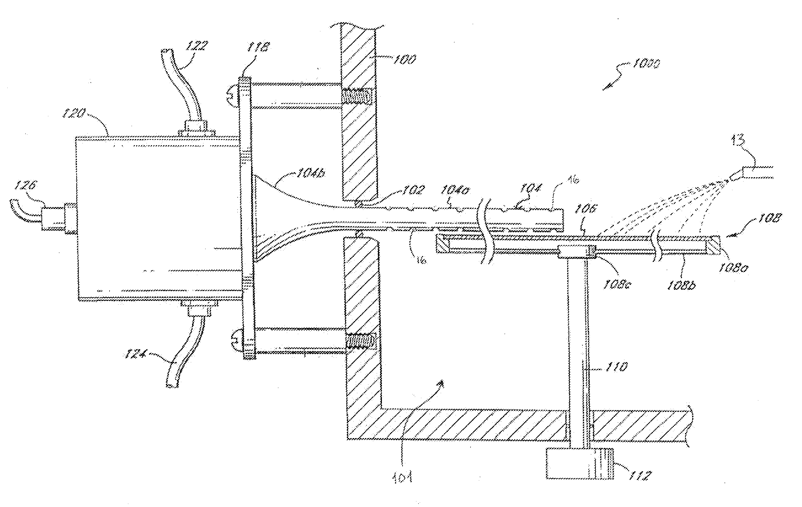
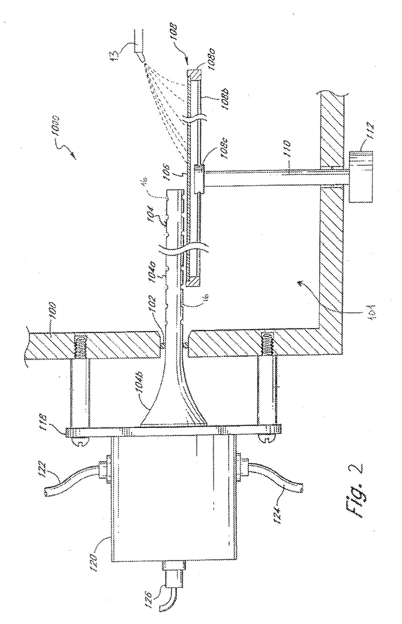
[0041] Referring first to FIGS. 2 and 3 concurrently, a side elevation view of an exemplary megasonic energy cleaning system 1000 (hereinafter referred to as the “cleaning system 1000”) is illustrated according to one embodiment of the present invention. For ease of discussion, the inventive system and methods of the drawings will be discussed in relation to the cleaning of substrates. It is to be understood that the invention can be utilized for any desired wet processing of any flat article, including without limitation semiconductor wafers.

[0042] The cleaning system 1000 has an elongated transmitter 104 inserted through the wall 100 of a processing tank 101. The transmitter 104 is supported in a cantilever fashion at one exterior end of the processing tank 101. An O-ring 102 is sandwiched between the transmitter 104 and the wall 100 to act as a seal for the processing tank 101. The transmitter 104 is acoustically coupled to a transducer 140 adapted to generate sonic energy. More...


PUM


Abstract

An apparatus, system and method for processing a substrate utilizing sonic energy. In one aspect, the invention utilizes a transmitter having through holes to dampen sonic energy that may damage the substrate. In other aspects, the through holes of the transmitter can be adapted to introduce a liquid solution having bubbles of a controlled size into the meniscus that couples the transmitter to the surface of a substrate to be cleaned to further dampen the sonic energy. IN one embodiment, the invention is a system for processing a substrate comprising: a rotary support for supporting a substrate in a substantially horizontal orientation; a transducer assembly comprising a transmitter and a transducer adapted to generate sonic energy, the transducer acoustically coupled to the transmitter; a plurality of internal passageways extending through the transmitter from holes in a first outer surface of the transmitter to holes in a second outer surface of the transmitter; and the transducer assembly positioned so that so that a portion of the vibration transmitter is adjacent to and spaced from a surface of a substrate on the rotary support so that when a liquid is applied to the surface of the substrate, a film of the liquid couples the portion of the transmitter to the surface of the substrate.

Description

CROSS-REFERENCE TO RELATED PATENT APPLICATION [0001] The present application claims the benefit of U.S. Provisional Application No. 60 / 830,254, filed on Jul. 12, 2006, the entirety of which is hereby incorporated by reference.FIELD OF THE INVENTION [0002] The present invention relates generally to the field of processing substrates utilizing sonic energy and, specifically, to apparatus, systems and methods for the megasonic-assisted cleaning of substrates that contain delicate devices, such as semiconductor wafers. BACKGROUND OF THE INVENTION [0003] In the field of semiconductor manufacturing, it has been recognized since the beginning of the industry that removing particles from semiconductor wafers during the manufacturing process is a critical requirement to producing quality profitable wafers. While many different systems and methods have been developed over the years to remove particles from semiconductor wafers, many of these systems and methods are undesirable because they ca...

Claims


Application Information

Patent Timeline
IPC IPC(8): B08B3/12H04R1/00
CPCB08B3/12
Inventor FRANKLIN, COLE
Owner NAURA AKRION INC
Why Eureka
Try Eureka