Method of dimming

a technology driving currents, applied in the direction of instruments, light sources, electroluminescent light sources, etc., can solve the problems of poor display quality, prior art cannot accurately control the luminance of light emitting diodes, delay time and rising time before stabilization, etc., to achieve control accurately luminance and improve display quality

Inactive Publication Date: 2012-01-26
CHUNGHWA PICTURE TUBES LTD
View PDF5 Cites 4 Cited by
  • Summary
  • Abstract
  • Description
  • Claims
  • Application Information

AI Technical Summary

Benefits of technology

[0010]A driving circuit for light emitting diodes, dimmer and method thereof provided by the present invention adjust the duty cycle of the original dimming signal to generate the dimming signal according to the driving current of the series of light emitting diodes and the ideal current. Then, the switch of the current sink can adjust the duty cycle of the driving current according to the dimming signal. Therefore, the driving circuit for light emitting diodes, dimmer and method thereof provided by the present invention can control accurately luminance of at least one series of light emitting diodes by adjusting the duty cycle of the driving current to improve a display quality.

Problems solved by technology

Due to original circuit conditions and design concerns regarding electromagnetic interference, when the driving current is turned on and turned off, the driving current for driving the light emitting diodes exhibits a delay time and a rising time before stabilizing.
Therefore, the prior art can not control accurately luminance of the light emitting diodes and has poorer display quality.

Method used


Image

  • Method of dimming
  • Method of dimming
  • Method of dimming

Examples


Embodiment Construction

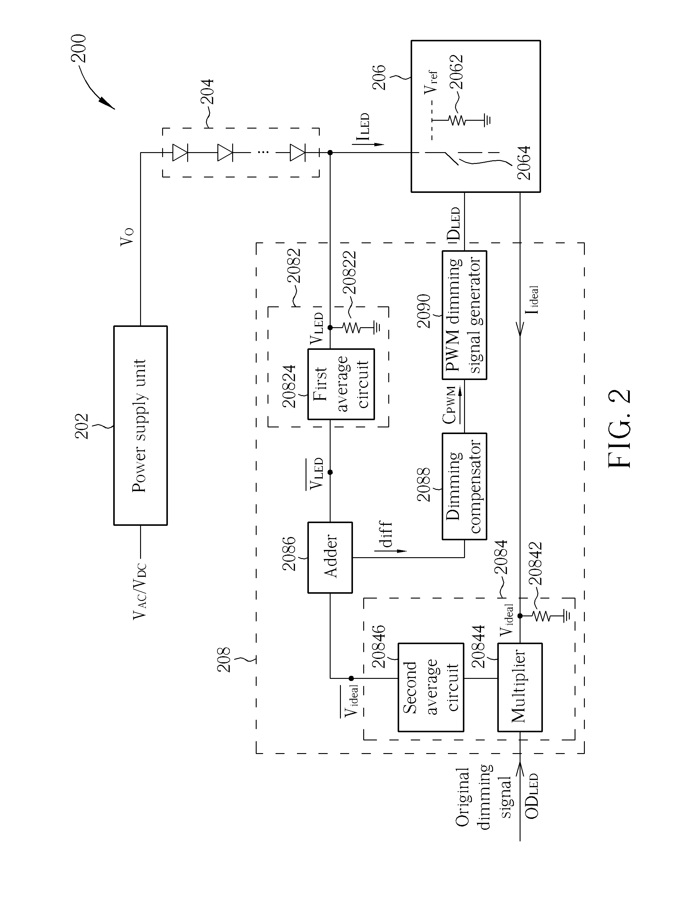
[0020]Please refer to FIG. 2. FIG. 2 is a diagram illustrating a driving circuit 200 for light emitting diodes capable of accurate dimming according to an embodiment of the present invention. The driving circuit 200 includes a power supply unit 202, a series of light emitting diodes 204, a current sink 206 and a dimming unit 208. The power supply unit 202 has an input terminal for receiving an AC voltage VAC or a DC voltage VDC, and an output terminal for providing a driving voltage Vo and a driving current ILED. The series of light emitting diodes 204 includes at least one light emitting diode, and the series of light emitting diodes 204 has a first terminal coupled to the output terminal of the power supply unit 202 for receiving the DC voltage Vo and the driving current ILED. The current sink 206 is coupled to a second terminal of the series of light emitting diodes 204, and the current sink 206 has a dimming control terminal for receiving a dimming signal DLED. In addition, the ...


PUM


Abstract

A power supply unit provides a voltage, and a driving current to a series of light emitting diodes. A dimming unit adjusts a duty cycle of an original dimming signal to generate a dimming signal according to the driving current and an ideal current. A current sink coupled to the series of light emitting diodes adjusts a duty cycle of the driving current according to the dimming signal.

Description

BACKGROUND OF THE INVENTION[0001]1. Field of the Invention[0002]The present invention is related to a driving circuit for light emitting diodes, dimmer and method thereof, and particularly to a driving circuit for light emitting diodes, dimmer and method thereof by adjusting a duty cycle of driving current to dim accurately.[0003]2. Description of the Prior Art[0004]Generally speaking, dimming methods of light emitting diodes (LEDs) backlights have two modes, a burst mode and a continuous mode, where the continuous mode is used for adjusting a peak of a driving current of the light emitting diodes. But, operation in the continuous mode may influence optical characteristics of a display, so the burst mode is the main dimming method for light emitting diodes.[0005]The burst mode dimming method controls turning-on or turning-off of driving current of light emitting diodes according to a pulse width modulation (PWM) dimming signal. Luminance of the LED is proportional to an average valu...

Claims


Application Information

Patent Timeline
Patent Type & Authority Applications(United States)
IPC IPC(8): H05B37/02
CPCH05B33/0848H05B33/0818H05B45/14H05B45/37
Inventor CHEN, CHIEN-YANGHSIEH, PO-KUNLAN, TUNG-HSINLIN, MING-CHANG
Owner CHUNGHWA PICTURE TUBES LTD
Why Eureka
Try Eureka