Display device and display control method

a display device and control method technology, applied in the field of display devices and display control methods, can solve the problems of output luminance, output luminance, output luminance differences among leds due to variation in deterioration property, etc., and achieve the reduction of luminance over an entire screen, correct luminance non-uniformity, and loss of display gray scales

Active Publication Date: 2014-07-29
SHARP KK
View PDF20 Cites 3 Cited by
  • Summary
  • Abstract
  • Description
  • Claims
  • Application Information

AI Technical Summary

Benefits of technology

[0038]As described above, a liquid crystal display device of the present invention includes: a display panel in which a plurality of pixels are arranged; a backlight section including (i) a plurality of light-emitting elements arranged in a matrix manner and (ii) a plurality of photosensors arranged in a matrix manner; a video signal processing section for carrying out a video signal process with respect to an input video signal supplied to the display device; a light-emitting element control section for carrying out control in which (i) an output luminance of a light-emitting element whose measured luminance is deviated from a reference luminance or (ii) output luminances of peripheral light-emitting elements which are provided around the light-emitting element is or are corrected, respectively, by use of control information of the plurality of light-emitting elements, which control information contains (a) information on measured luminances of the plurality of light-emitting elements, the information being obtained by the plurality of photosensors and (b) positional information of the plurality of light-emitting elements, the positional information being obtained by the plurality of photosensors, and; a display control section for controlling, on the basis of (i) a plurality of video signals which have been subjected to the video signal process and are supplied from the video signal processing section and (ii) the control information supplied from the light-emitting element control section, (a) levels of video signals to be supplied to pixels corresponding to the light-emitting element, whose output luminance is corrected or (b) levels of video signals to be supplied to pixels corresponding to the peripheral light-emitting elements, whose output luminances are corrected, the reference luminance being a luminance which is originally expected to be outputted from each of the plurality of light-emitting elements.
[0039]As described above, a liquid crystal display device of the present invention includes: a display panel in which a plurality of pixels are arranged; a backlight section including (i) a plurality of light-emitting elements arranged in matrix and (ii) a plurality of photosensors arranged in matrix; a video signal processing section for carrying out a video signal process on a plurality of input video signals supplied to the display device; and an area driving section for (i) dividing a display region, which is constituted by the plurality of pixels as a whole, into a plurality of small regions and (ii) supplying, as light-emitting element data and to corresponding one of the plurality of light-emitting elements, an output luminance modulated in accordance with a level of a video signal, out of the plurality of video signals, to be supplied to a pixel contained in one of the plurality of small regions, the area driving section including a light-emitting element correcting section and a luminance data creating section, the light-emitting element correcting section creating a light-emitting element correction signal by use of (i) the light-emitting element data supplied from the area driving section, (ii) the information on the measured luminances of the plurality of light-emitting elements, the information being obtained by the plurality of photosensors, and (iii) the positional information of the plurality of light-emitting elements, the positional information being also obtained by the plurality of photosensors, the light-emitting element correction signal being a signal for correcting (a) an output luminance of a specific light-emitting element whose measured luminance is deviated from a reference luminance or (b) an output luminance of a peripheral light-emitting element which is provided around the specific light-emitting element, the luminance data creating section controlling a level of a video signal, out of the plurality of video signals, to be supplied to (a) the specific light-emitting element, whose output luminance is corrected or (b) the peripheral light-emitting element, whose output luminance is corrected, control of the level of the video signal being carried out so that transmittances of a plurality of pixels centered about a pixel corresponding to a center of the specific light-emitting element have a transmittance distribution which exhibits a change reverse to that of a luminance distribution of the specific light-emitting element and the peripheral light-emitting element.
[0040]As described above, a display control method for a display device of the present invention is a display control method which includes the steps of: correcting luminances of peripheral light-emitting elements, which are provided around a specific light-emitting element, so as to compensate a luminance deviation of the specific light-emitting element from a reference luminance; and correcting transmittances of peripheral pixels, located around a pixel corresponding to a center of the specific light-emitting element so that the peripheral pixels have transmittance distributions which exhibit respective changes reverse to those of a luminance distribution of the specific light-emitting element and the peripheral light-emitting elements.
[0041]Therefore, it becomes possible to provide a display device and a display control method which can correct luminance non-uniformity of or a color drift in a display plane, which is caused by differences in the luminance of a backlight and / or aged deterioration, without causing (i) a reduction in luminance over an entire screen and (ii) a loss in display gray scales.

Problems solved by technology

A liquid crystal display device employing a backlight unit and a liquid crystal panel has conventionally had a problem of in-plane luminance non-uniformity.
What are particularly seen as problems in such a backlight unit are (i) individual differences in output luminance among LEDs and (ii), in a case where LEDs of colors R, G, and B are used, differences in output luminance among the LEDs due to variation in deterioration property among the LEDs of the respective colors.
This ultimately causes the in-plane luminance non-uniformity.
This causes the in-plane luminance non-uniformity.

Method used


Image

  • Display device and display control method
  • Display device and display control method
  • Display device and display control method

Examples


example 1

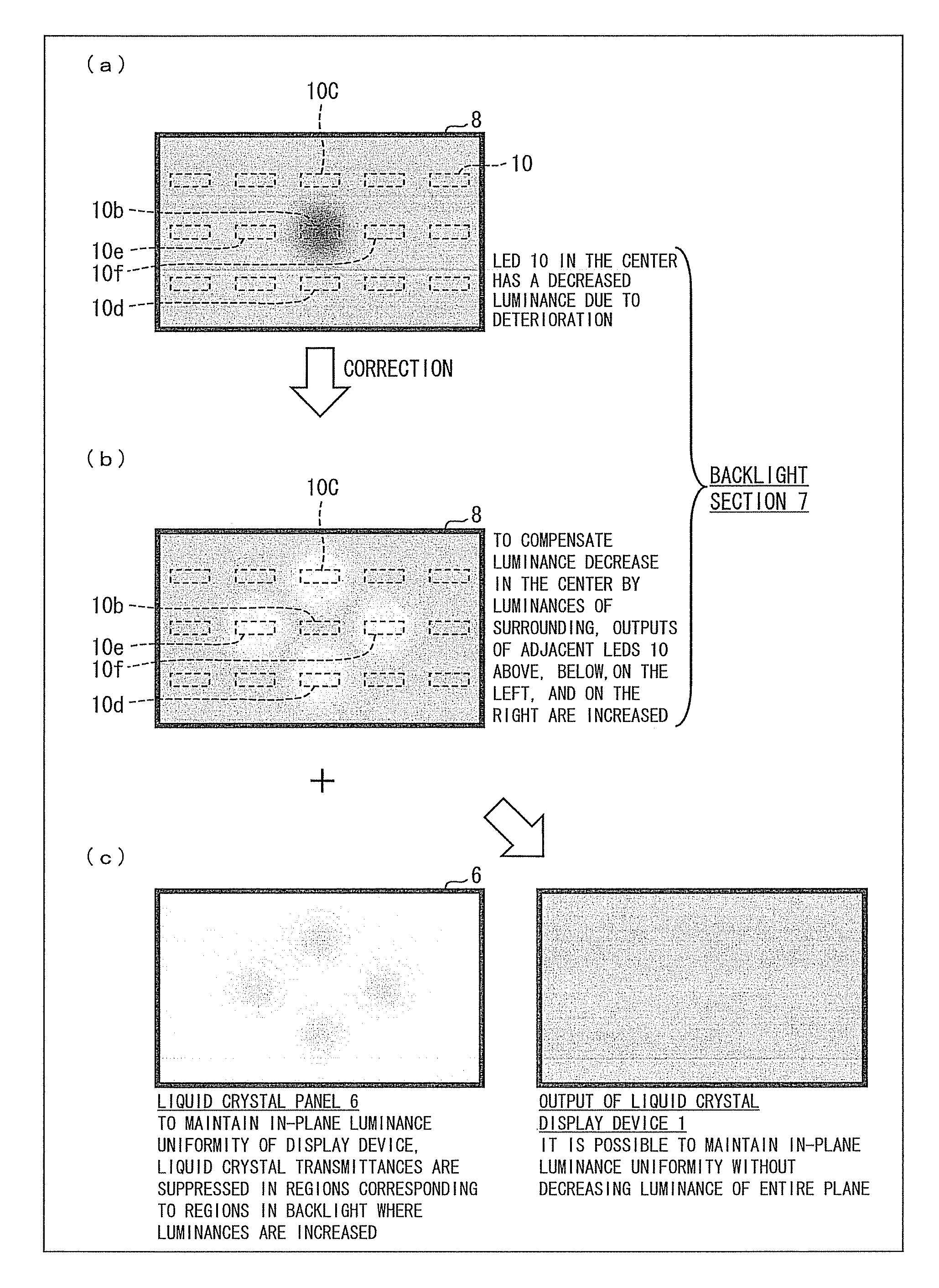
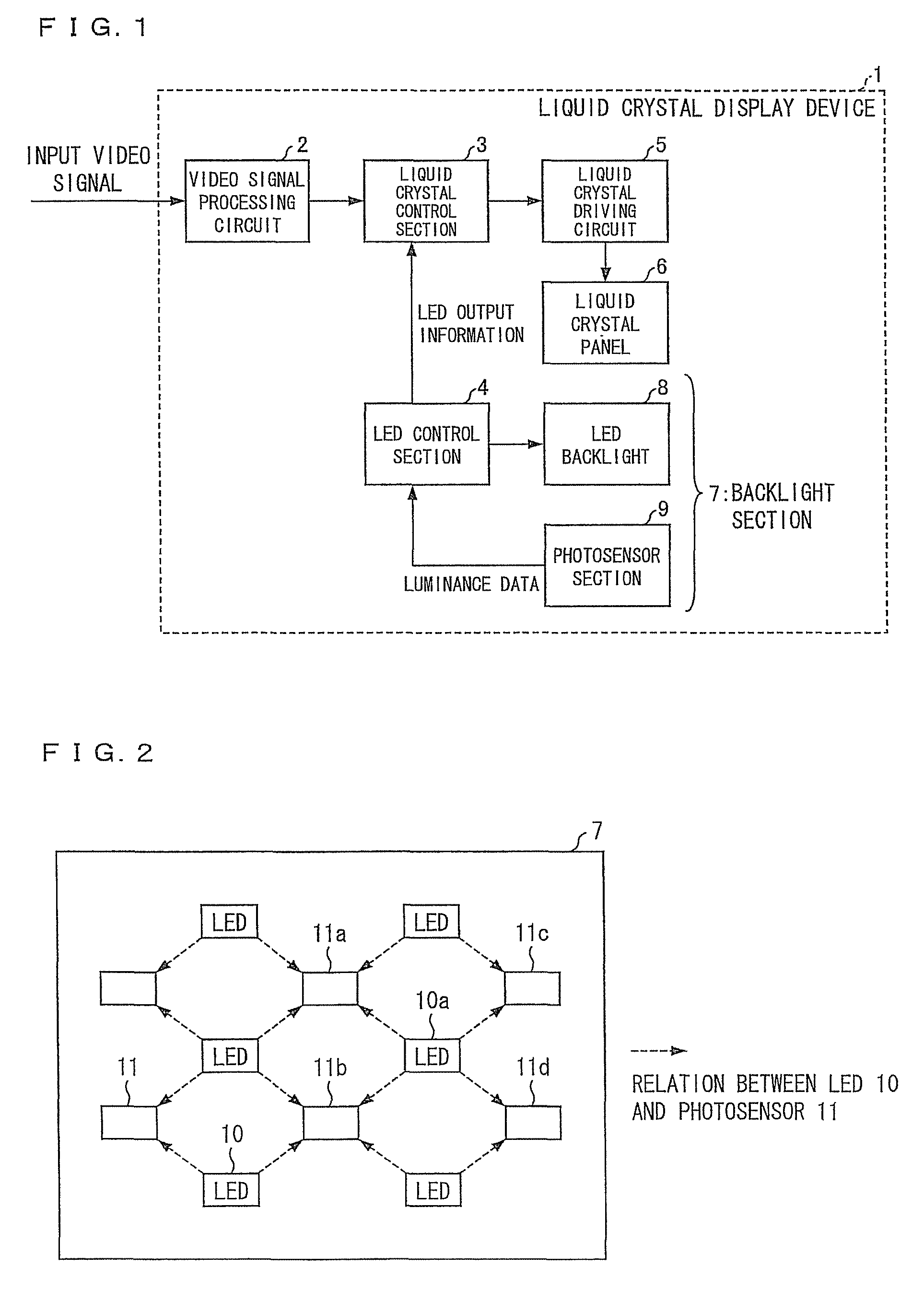
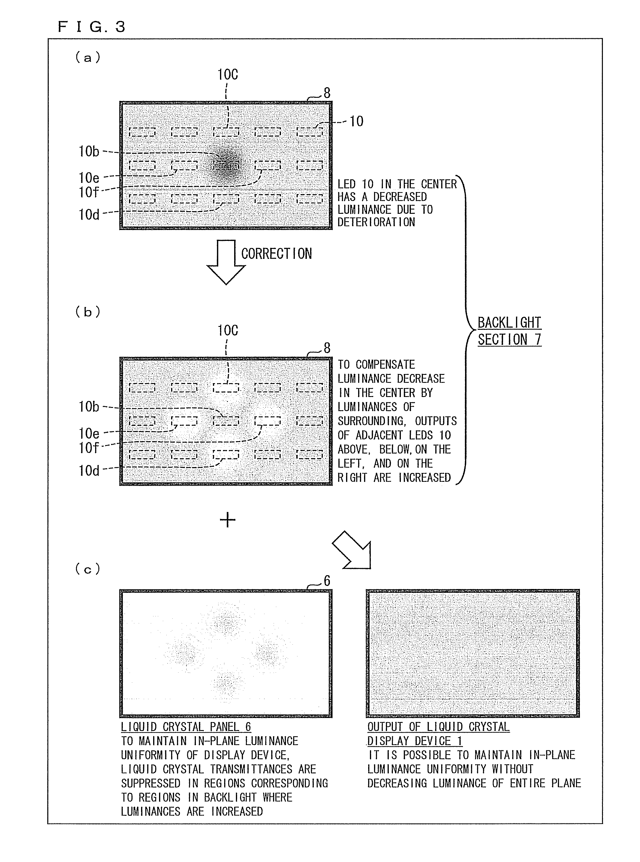
[0053]FIG. 1 is a block diagram of a liquid crystal display device (display device) 1 in accordance with Example 1. The liquid crystal display device 1 includes a video signal processing circuit (video signal processing section) 2, a liquid crystal control section (display control section) 3, an LED control section (light-emitting element control section) 4, a liquid crystal driving circuit 5, a liquid crystal panel (display panel) 6, and a backlight section 7. A plurality of pixels are arranged in the liquid crystal panel 6. The backlight section 7 includes (i) an LED backlight 8, in which a plurality of LEDs (light-emitting elements) 10 (see FIG. 2) are provided and (ii) a photosensor section 9, in which a plurality of photosensors 11 (see FIG. 2) are provided.

[0054]The liquid crystal display device 1 employs the LED backlight 8, which is a direct backlight in which the plurality of LEDs 10 are arranged in a matrix manner. Note that the liquid crystal display device 1 does not car...

example 2

[0089]Another example of the present invention will be described below with reference to FIGS. 5 and 6. Note that configurations of Example 2 other than configurations to be described in Example 2 are the same as those of early-described Example 1. For easy explanation, the same reference signs will be given to members each having the same function as a member illustrated in the figures of Example 1, and descriptions on such a member will be omitted.

[0090]FIG. 5 is a block diagram showing a liquid crystal display device 12 in accordance with Example 2. The liquid crystal display device 12 is different from the liquid crystal display device 1 illustrated in FIG. 1 in that an area active driving circuit (area driving section) 13 is provided. The area active driving circuit 13 supplies, to the LED control section 4, output luminances modulated in accordance with levels of video signals to be supplied to pixels in one of a plurality of regions into which a display region, which is const...

example 3

[0121]A further example of the present invention will be described below with reference to FIGS. 7 and 8. Note that configurations of Example 3 other than configurations to be described in Example 3 are the same as those of early-described Examples 1 and 2. For easy explanation, the same reference signs will be given to members each having the same function as a member illustrated in the figures of Examples 1 and 2, and descriptions on such a member will be omitted.

[0122]FIG. 7 is a block diagram showing a liquid crystal display device 23 in accordance with Example 3. The liquid crystal display device 23 is different from the liquid crystal display device 12 illustrated in FIG. 2 in that (i) no liquid crystal control section 3 and no LED control section 4 are provided and (ii) an LED correcting section (light-emitting element correcting section) 24 is provided in the LED data calculation section 16.

[0123]In the liquid crystal display device 23 illustrated in FIG. 7, the LED correcti...


PUM

PropertyMeasurementUnit
transmittanceaaaaaaaaaa
luminanceaaaaaaaaaa
transmittanceaaaaaaaaaa

Abstract

A display device includes: an LED control section (4) for carrying out control in which (i) an output luminance of an LED (10) whose measured luminance is deviated from a reference luminance or (ii) output luminances of peripheral LEDs (10) which are provided around the LED (10) is or are corrected, respectively, by using control information of the plurality of LEDs, which control information contains (a) information on measured luminances of the plurality of LEDs, the information being obtained by the plurality of photosensors (11) and (b) positional information of the plurality of LEDs, the positional information being obtained by the plurality of photosensors (11), and a liquid crystal display control section (3) for controlling, based on (i) video signals which have been subjected to the video signal process and are supplied from a video signal processing section (2) and (ii) the control information supplied from the LED control section (4), (a) levels of video signals to be supplied to pixels corresponding to the LED (10), whose output luminance is corrected or (b) levels of video signals to be supplied to pixels corresponding to the peripheral LEDs, whose output luminances are corrected, the reference luminance being a luminance which is originally expected to be outputted from each of the plurality of LEDs.

Description

TECHNICAL FIELD[0001]The present invention relates to a display device and a display control method.BACKGROUND ART[0002]A liquid crystal display device employing a backlight unit and a liquid crystal panel has conventionally had a problem of in-plane luminance non-uniformity. The in-plane luminance non-uniformity is caused by, for example, (i) individual differences among light sources used in the backlight unit and / or (ii) in-plane transmittance (optical transmittance) non-uniformity of the liquid crystal panel.[0003]As for the backlight unit, a backlight unit in which a plurality of LED light sources are arranged has been provided in recent years. What are particularly seen as problems in such a backlight unit are (i) individual differences in output luminance among LEDs and (ii), in a case where LEDs of colors R, G, and B are used, differences in output luminance among the LEDs due to variation in deterioration property among the LEDs of the respective colors.[0004]In a case wher...

Claims


Application Information

Patent Timeline
Patent Type & Authority Patents(United States)
IPC IPC(8): G09G5/00G02F1/1335G09G3/34G09G3/36G09G5/10
CPCG09G3/3426G09G2320/0646G09G2360/141G09G2360/142G09G2320/0242G02F1/133603G09G2320/062G09G2320/0626
Inventor UENO, MASAFUMIFURUKAWA, HIROYUKIYOSHIYAMA, KAZUYOSHIOHKI, YASUHIROTAKASE, KENJIISHIZUMI, TAKASHI
Owner SHARP KK
Why Eureka
Try Eureka