Thermal device

a technology of thermal devices and skin, applied in the direction of contraceptive devices, therapeutic cooling, therapeutic heating, etc., can solve the problems of gradual rise in skin side temperature, increased heat generation rate during wear, and difficult to detect, so as to improve skin health

Inactive Publication Date: 2012-01-26
WYETH LLC
View PDF1 Cites 15 Cited by
  • Summary
  • Abstract
  • Description
  • Claims
  • Application Information

AI Technical Summary

Benefits of technology

[0019]The present invention also includes methods of providing consistent skin side temperature, methods of improving skin health and methods of providing passive skin side temperature control, by applying to a user's skin devices comprising a primary insulative material disposed between a thermal source and a user's skin; wherein the device provides a rate of change in skin side temperature to change in thermal source temperature of less than about 0.8. i.e. for every change of 1° C. of a thermal source temperature, there is a change of less than about 0.8° C. in the skin side temperature of the device.

Problems solved by technology

However, actual use conditions are often different.
In addition, heat generation rate can be increased during wear due, for example, to body movement that increases air flow to an exothermic composition.
In addition, generally, such a rise in skin side temperature is gradual and not easily perceptible by the user even when it approaches or exceeds 43° C. Thus, injury can occur slowly, without the user noticing until it is too late and the skin has been burned.
However, phase change materials have a finite heat absorption capacity and are expensive.
Thus, they would not be practical for heat wraps used for therapeutic pain relief where 8 hours or more of heat is required.
Therefore preventing overly hot exothermic compositions can be difficult and / or expensive.
However, in practice, controlling heat generation via controlling air flow is difficult, because for example body movement can affect air flow.
However, high temperature during transportation and in storage conditions could prematurely release the quenching agents prior to use of the device and render the device ineffective.

Method used


Image

  • Thermal device
  • Thermal device
  • Thermal device

Examples


examples

[0088]The following non-limiting examples further describe and demonstrate embodiments within the scope of the present invention. The examples are given solely for the purpose of illustration and are not to be construed as limitations of the present invention, as many variations thereof are possible without departing from the spirit and scope of the present invention.

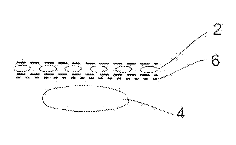
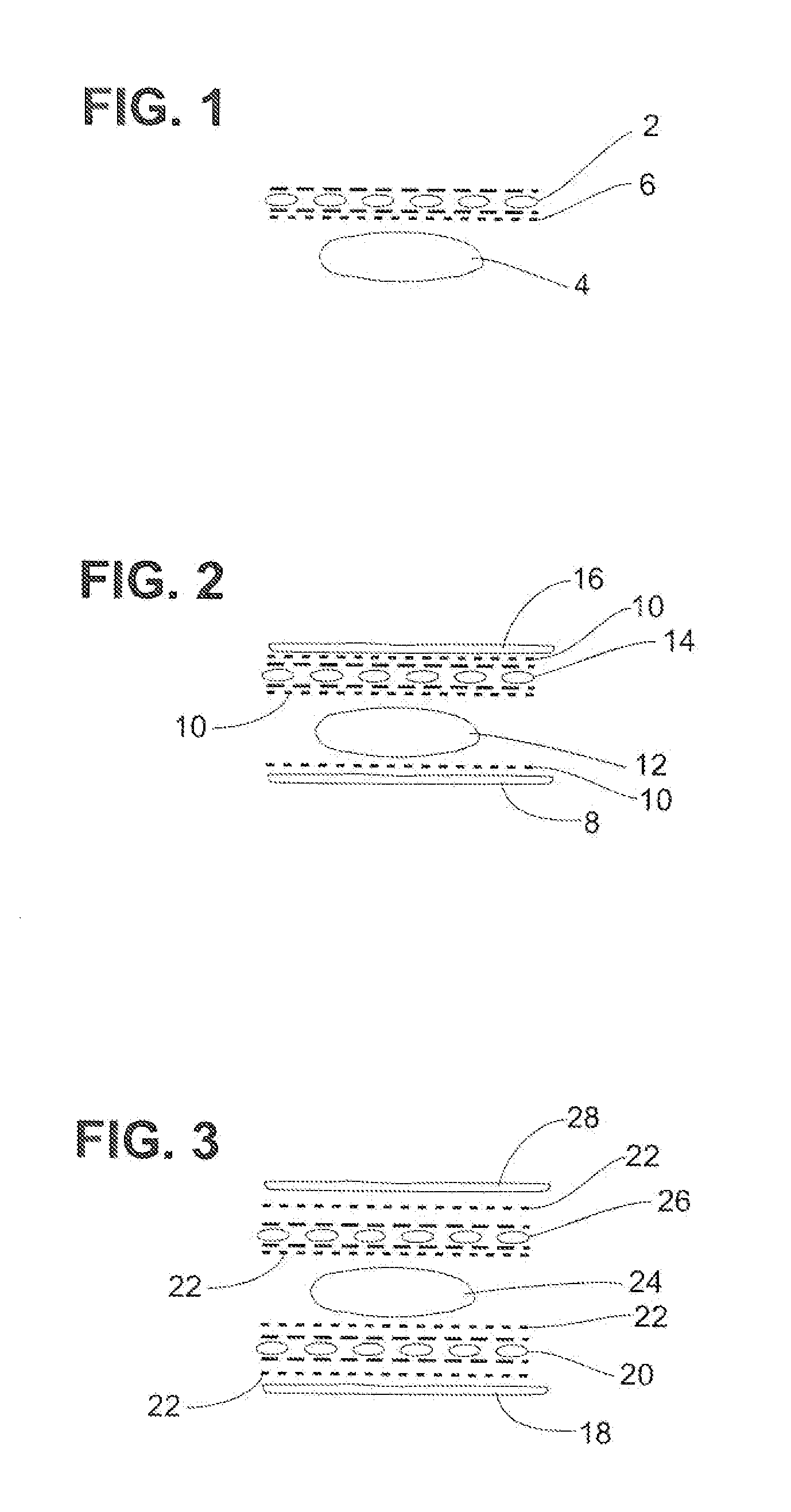
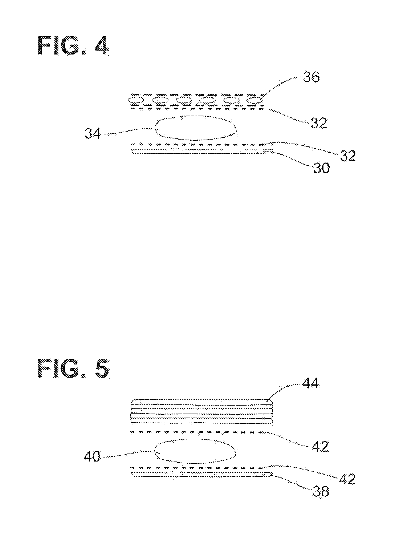
[0089]The schematic illustrations of FIGS. 1-5 are used only to represent the arrangement and order of components that can form the devices of the present invention. They are not drawn to scale. All thermal sources of FIGS. 1-5 are shown as an oval shaped area which is used for illustrative purposes only and does not represent any particular thermal source, nor proportional size or shape of any such thermal source.

[0090]FIG. 1 is a schematic illustration of an embodiment of the present invention in which a primary insulative material 2 is disposed on a skin side of a thermal source 4, and attached thereto by constructio...


PUM


Abstract

A method of delivering safe therapeutic heat to an unconscious or inert subject is described, wherein a disposable device is applied to the user that provides a consistent skin side temperature, wherein said device comprises a thermal source comprising a particulate exothermic composition; and a primary insulative material disposed on a skin side of the thermal source that delivers heat while protecting the subject from burns; wherein said device provides a rate of temperature change of less than about 0.8.

Description

CROSS REFERENCE TO RELATED APPLICATION[0001]This application is a continuation-in-part (CIP) of U.S. application Ser. No. 12 / 052,296, filed on Mar. 20, 2008, which claims the benefit of U.S. Provisional Application No. 60 / 919,008, filed on Mar. 20, 2007, the contents for both of which are hereby incorporated by reference as if set forth fully herein.FIELD OF THE INVENTION[0002]The present invention relates to devices and methods for providing consistent skin side temperature of a thermal device during use. The devices and methods of the invention provide a rate of change in temperature of less than about 0.8.BACKGROUND OF THE INVENTION[0003]Disposable and reusable devices such as heat wraps have become a popular way to apply heat for relief of discomfort from temporary or chronic aches, pains, and injuries. Common heat wraps, for example, typically comprise a heat source containing an exothermic composition that generates heat, wherein the exothermic composition comprises metal powd...

Claims


Application Information

Patent Timeline
Patent Type & Authority Applications(United States)
IPC IPC(8): A61F7/08
CPCA61F7/034A61F2007/0249A61F2007/0228
Inventor WONG, VINCENT YORK-LEUNGFREELAND, MARY ELAINEEBEL, JAMES PATRICK
Owner WYETH LLC
Why Eureka
Try Eureka