Projected capacitive panel

Active Publication Date: 2012-02-16
TRENDON TOUCH TECHNOLOGY CORPORATION
View PDF7 Cites 5 Cited by
  • Summary
  • Abstract
  • Description
  • Claims
  • Application Information

AI Technical Summary

Benefits of technology

[0011]An objective of the present invention is to provide a projected capacitive touch panel preventing signal transmission lines thereon in the X and

Problems solved by technology

Usually, the longer the signal transmission distance is, the lower the capability against interference is.
Furthermore, as the X-axis signal transmission lines and the Y-axis signal transmission lines must be commonly connected to a circuit board and concentrated on one side of the touch panel, the width of the side frame of the touch panel for accommodating the layout of the X-axis signal transmission

Method used


Image

  • Projected capacitive panel
  • Projected capacitive panel
  • Projected capacitive panel

Examples


Embodiment Construction

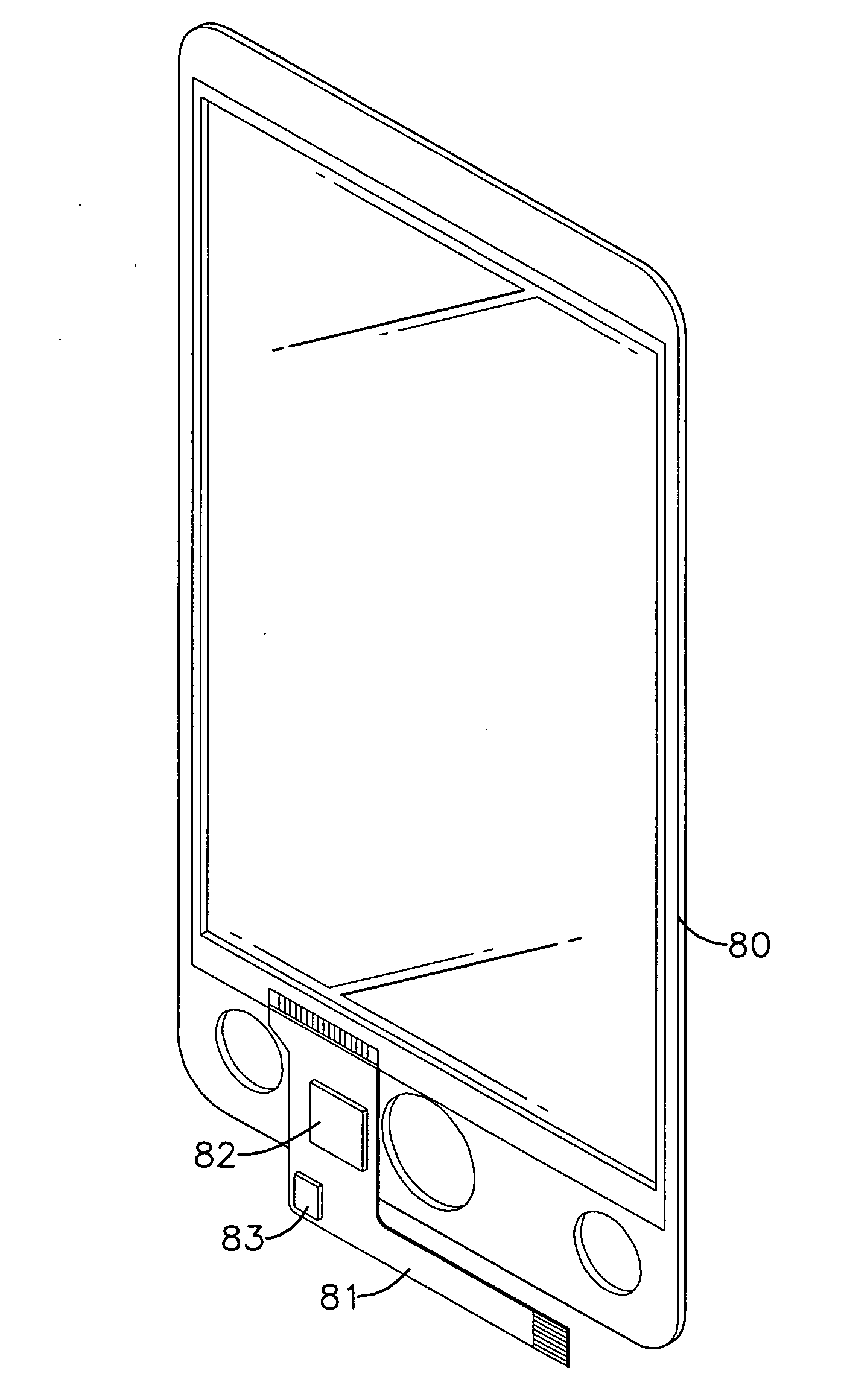
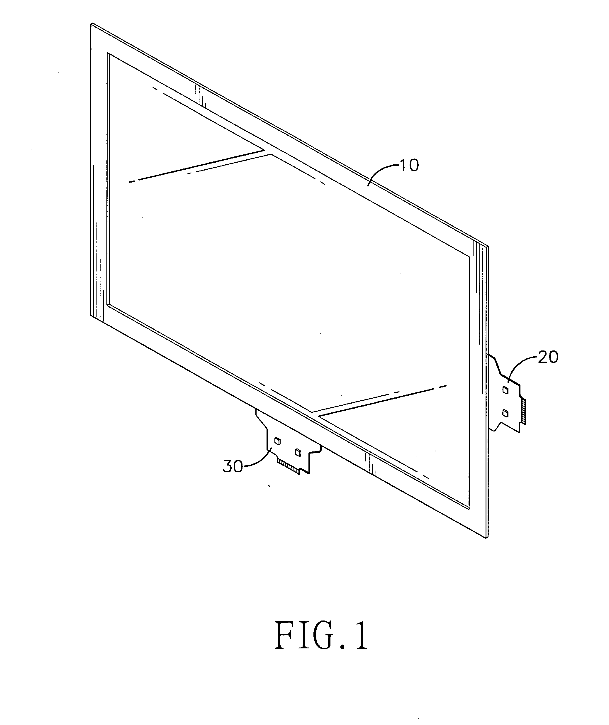
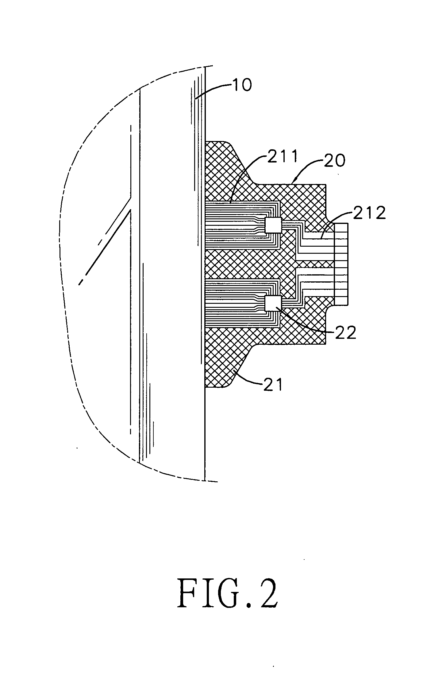
[0032]With reference to FIG. 1, a first embodiment of a touch panel 10 is rectangular and has a substrate, an X-axis electrode layer, a Y-axis electrode layer, an X-axis conversion module 20 and a Y-axis conversion module 30.

[0033]In the present embodiment, the touch panel is a projected capacitive touch panel. The substrate has a top, a bottom, two short sides and two long sides. The X-axis electrode layer is mounted on the top of the substrate and has a plurality of X-axis signal transmission lines and a plurality of X-axis electrodes. The X-axis signal transmission lines are formed on the substrate and are adjacent to one of the short sides of the substrate. The X-axis electrodes are arranged as a matrix. The X-axis electrodes on each row of the X-axis electrodes are mutually connected. The X-axis electrode located on one end of the row is further connected with an X-axis signal transmission line. The Y-axis electrode layer is mounted on the bottom of the substrate and has a plur...


PUM


Abstract

A projected capacitive touch panel has a substrate, an X-axis electrode layer formed on a top of the substrate and a Y-axis electrode layer formed on a bottom of the substrate. The X-axis and the Y-axis electrode layers respectively have a plurality of X-axis electrodes and Y-axis electrodes arranged in a matrix form and respectively connected with a plurality of X-axis and Y-axis signal transmission lines. Each of the X-axis signal transmission lines and the Y-axis signal transmission lines is connected with a conversion module. The conversion modules is mounted to be adjacent to the X-axis and Y-axis signal transmission lines, converts analog signals into relatively stable digital signals, and transmits the digital signals to an external controller to determine coordinates being touch. Accordingly, lengths of the X-axis and Y-axis signal transmission lines can be shortened and the size of a control area of the touch panel can be enlarged.

Description

BACKGROUND OF THE INVENTION[0001]1. Field of the Invention[0002]The present invention relates to a touch panel, and more particularly to a projected capacitive touch panel effectively enlarging the size of the touch panel and preventing signal transmission lines thereon in the X and Y directions from being overlong.[0003]2. Description of the Related Art[0004]Current touch panels are classified as capacitive touch panels and resistive touch panels. For sake of lower cost, the resistive touch panels have larger market share of all sorts of touch panels. Since Apple's iPHONE emergence to the touch panel market, in addition to the wide range of touch control, the multi-point touch function has become one of the best selling points. However, the multi-point touch feature originates from the projected capacitive touch panels, which also pertain to one type of capacitive touch panels.[0005]With reference to FIG. 6, a conventional projected capacitive touch panel has a substrate 70, an X-a...

Claims


Application Information

Patent Timeline
IPC IPC(8): G06F3/041
CPCG06F3/044G06F3/0445G06F3/0446
Inventor MI, DAVID
Owner TRENDON TOUCH TECHNOLOGY CORPORATION
Why Eureka
Try Eureka