Composite transformer and insulated switching power source device

a technology of switching power source device and composite transformer, which is applied in the direction of transformer/inductance coil/winding/connection, inductance, printed electric component incorporation, etc., can solve the problems of large area needed for pattern wiring, interference between individual transformer units, and malfunction of electronic devices using transformer units, so as to reduce the loss, less interference, and the effect of less al valu

Active Publication Date: 2011-01-18
MURATA MFG CO LTD
View PDF13 Cites 43 Cited by
  • Summary
  • Abstract
  • Description
  • Claims
  • Application Information

AI Technical Summary

Benefits of technology

[0016]Accordingly, the present disclosure presents a composite transformer having the above-described improvements, namely, less interference between a plurality of transformer units, less loss, and less decrease in an AL value.

Problems solved by technology

First, there exists the possibility of occurrence of a failure in which interference occurs between individual transformer units due to a manufacturing problem.
However, when a small gap exists at the joint of either one of the outer legs due to dust or the like, interference due to the two legs occurs, resulting in malfunction of an electronic device using the transformer units, depending on the degree of the interference.
Second, a large area is necessary for pattern wiring.
However, when the distance between the two outer legs is large, the length of the two wires is large, which leads to a large area being necessary for pattern wiring.
When the first transformer unit receives a high power, loss is increased due to an increase in the resistance of the coil.
Thus, loss increases when the exciting inductance decreases.
Further, when the number of turns of the coil in the second transformer unit is increased while the second transformer unit interferes with the first transformer unit, the interference voltage increases with increasing number of turns.
This leads to malfunction of an electronic apparatus using such a transformer.

Method used


Image

  • Composite transformer and insulated switching power source device
  • Composite transformer and insulated switching power source device
  • Composite transformer and insulated switching power source device

Examples


first embodiment

[0090]A transformer according to a first embodiment will be described on the basis of FIGS. 3(A)-4(B).

[0091](E) and (F) in FIG. 3 are cross-sectional views of main parts of a transformer. As illustrated in these FIGS. 3(E) and 3(F), the transformer is composed primarily of a printed board 110, an E-shaped core 106, and an I-shaped core 107.

[0092]FIG. 3(A) is a plan view of a first printed coil layer of the printed board 110 which is a multilayer substrate, (B) is a plan view of a second printed coil layer of the printed board 110, (C) is a plan view of a third printed coil layer of the printed board 110, and (D) is a plan view of a fourth printed coil layer of the printed board 110. These plan views includes the cross-sections of leg portions of the E-shaped core 106.

[0093]As illustrated in FIG. 3, the E-shaped core 106 has a middle leg 106b and a pair of outer legs 106a and 106c on opposite sides with respect to the middle leg 106b. In addition, the outer leg 106a is divided in the...

second embodiment

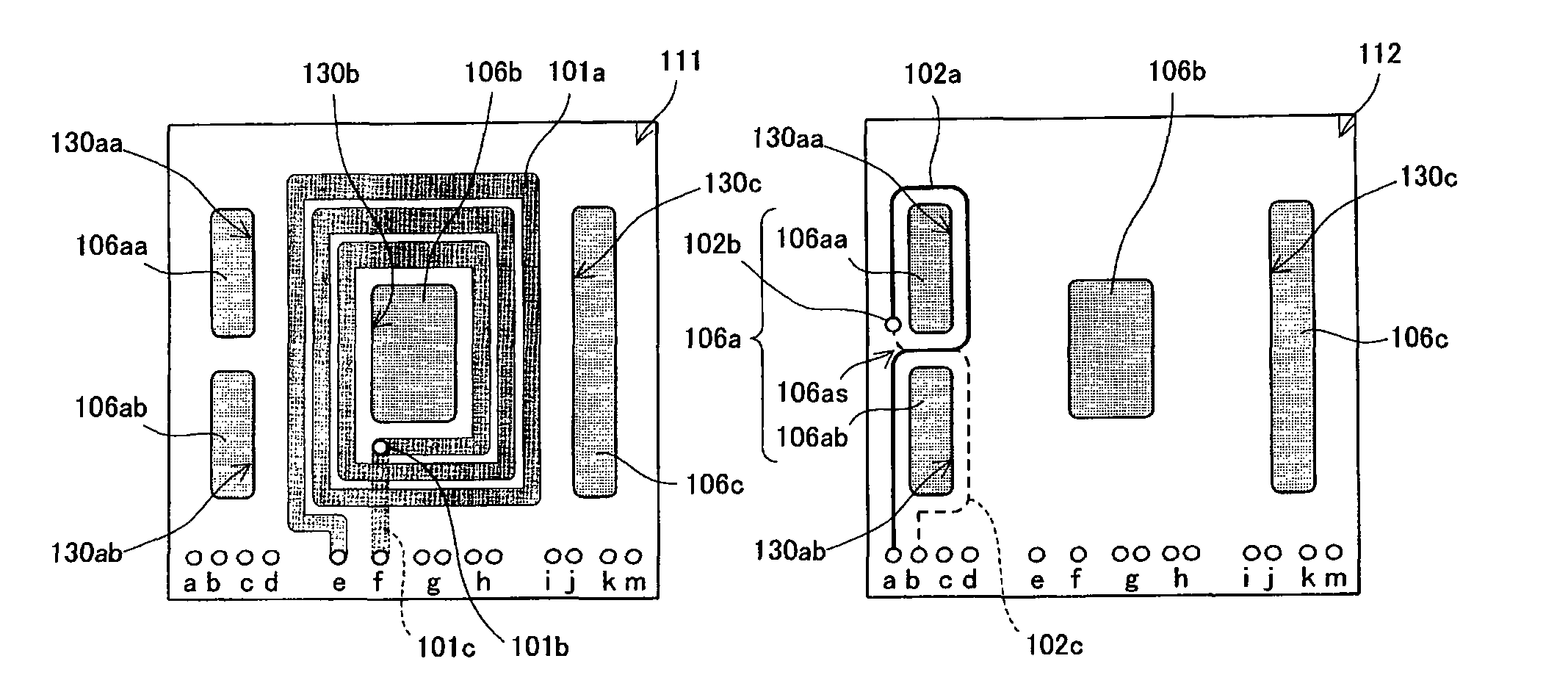
[0115]In the following, a transformer according to a second embodiment will be described with reference to FIG. 5.

[0116]FIG. 5 shows diagrams illustrating examples of wiring formed on a printed board used in the transformer according to the second embodiment. Note that for convenience of the description, the examples are shown in two layers, without illustration of four layers as in the case of FIG. 3. In the first embodiment, a four-leg core is used. However, in this second embodiment, a five-leg core is used, and one power transmission transformer unit and two signal transmission transformer units are provided.

[0117]The cross-sectional structure of the entire transformer is substantially the same as that described in the first embodiment, and thus the illustration thereof will be omitted and only parts different from the first embodiments will be hereinafter described.

[0118]An E-shaped core 106 has a middle leg 106b and one pair of outer legs 106a and 106c on opposite sides with r...

third embodiment

[0120]In the following, a transformer according to a third embodiment will be described with reference to FIG. 6.

[0121](E) and (F) in FIG. 3 illustrate a configuration in which the printed board 110 are sandwiched by the E-shaped care 106 and the I-shaped core 107. However, in this third embodiment, a detailed configuration for keeping the E-shaped core 106 and the I-shaped core 107 in an attached state.

[0122](A) in FIG. 6 is a plan view of a transformer formed together with a printed board 110, (B) is a right-side plan view of the transformer, and (C) is a front elevation view of the transformer.

[0123]The E-shaped core 106 and the I-shaped core 107 are fitted to each other by a core fixing metal member 108. The core fixing metal member 108 includes four claw portions 108f for engaging with the E-shaped core 106 at four points of the edges of the E-shaped core 106, a core side supporting portion 108s for supporting a center part of two longer edges of the I-shaped core, spring porti...


PUM

PropertyMeasurementUnit
voltageaaaaaaaaaa
drain voltageaaaaaaaaaa
temperatureaaaaaaaaaa

Abstract

An E-shaped transformer core has a middle leg and one pair of outer legs and on opposite sides with respect to the middle leg. A first pair of coils including at least two coils are wound around the middle leg so that a power transmission transformer unit is formed. The outer leg is divided into two outer leg portions and with a space therebetween allowing coil wiring therebetween, and a second pair of coils including two coils are respectively wound around the respective two outer leg portions and so as to have mutually opposite winding directions, so that a signal transmission transformer unit is formed.

Description

CROSS-REFERENCE TO RELATED APPLICATIONS[0001]This is a continuation under 35 U.S.C. §111(a) of PCT / JP2006 / 321711 filed Oct. 31, 2006, and claims priority of JP2005-363129 filed Dec. 16, 2005, incorporated by reference.BACKGROUND[0002]1. Technical Field[0003]The present disclosure relates to a composite transformer which is provided with a plurality of transformer units and has functions of power transmission and voltage conversion between primary and secondary and also a function of signal transmission between primary and secondary.[0004]2. Background Art[0005]Patent Document 1, Japanese Unexamined Patent Application Publication No. 2000-260639, discloses an arrangement in which a plurality of transformer units which can be regarded as being independent of each other are formed using a pair of cores.[0006]FIGS. 1(A)-1(D) and FIG. 2 are diagrams illustrating an example of a configuration of a transformer according to Patent Document 1. FIGS. 1(A)-1(D) are diagrams illustrating patter...

Claims


Application Information

Patent Timeline
Patent Type & Authority Patents(United States)
IPC IPC(8): H01F5/00
CPCH01F27/2804H02M3/33592H01F17/0013H01F2027/065H05K1/165Y02B70/1475Y02B70/10
Inventor MATUMOTO, TADAHIKO
Owner MURATA MFG CO LTD
Why Eureka
Try Eureka