Implantable medical electrode device

a medical electrode and implantable technology, applied in the field of medical devices and implantable electrode devices, can solve the problems of complex construction, prone to breakdown, and snags of anchoring elements on other body structures,

Inactive Publication Date: 2013-04-23
BIOTRONIK SE & CO KG
View PDF7 Cites 42 Cited by
  • Summary
  • Abstract
  • Description
  • Claims
  • Application Information

AI Technical Summary

Benefits of technology

[0005]Proceeding therefrom, the present invention is based on the object of improving the known electrode devices in regard to their anchoring elements in such a way that implantation and explantation of the electrode device with less interference, but nonetheless reliable fixing, are ensured.
[0007]This design results in the implanter setting the electrode body in rotation in the rotational direction in which he feels a lower rotational resistance, if the anchoring elements snag in the valve leaflets, for example. This rotation anisotropy may, for example, be achieved by a tilted configuration of anchoring elements in relation to a radial plane spanned by the electrode body axis and the base point of the particular anchoring element. The strut-like anchoring elements thus project diagonally from the electrode body in relation to the peripheral direction. This means that they stand up upon rotation in one direction in the event of an external resistance, such as the trabeculae in the heart, and thus tangle more strongly with the surrounding tissue. Upon a rotation in the opposite direction, the anchoring elements adapt to the electrode body, so that they disengage from the external tissue and the electrode body is thus simpler to withdraw from its fixing in the trabeculae or easier to detach from a snag in the valve leaflets, for example.
[0010]The latter also implements a concept of the present invention, namely the anisotropic resistance in relation to the rotation of the electrode body. Thus, for example, spreading of the projecting lamellae may be achieved by a right rotation of the electrode body, which causes secure anchoring of the electrode in the vessel.

Problems solved by technology

In the known electrode devices, the problem may occur that the anchoring elements may snag on other body structures, for example, in the valve leaflets, during insertion or withdrawal of the catheter.
This results in the electrode having to be freed using a relatively strong pull on the electrode body, which may result in local damage to the cardiac tissue.
However, this has a very complex construction and is also susceptible to breakdown because of the very fine structures of the anchoring elements.

Method used


Image

  • Implantable medical electrode device
  • Implantable medical electrode device
  • Implantable medical electrode device

Examples


Embodiment Construction

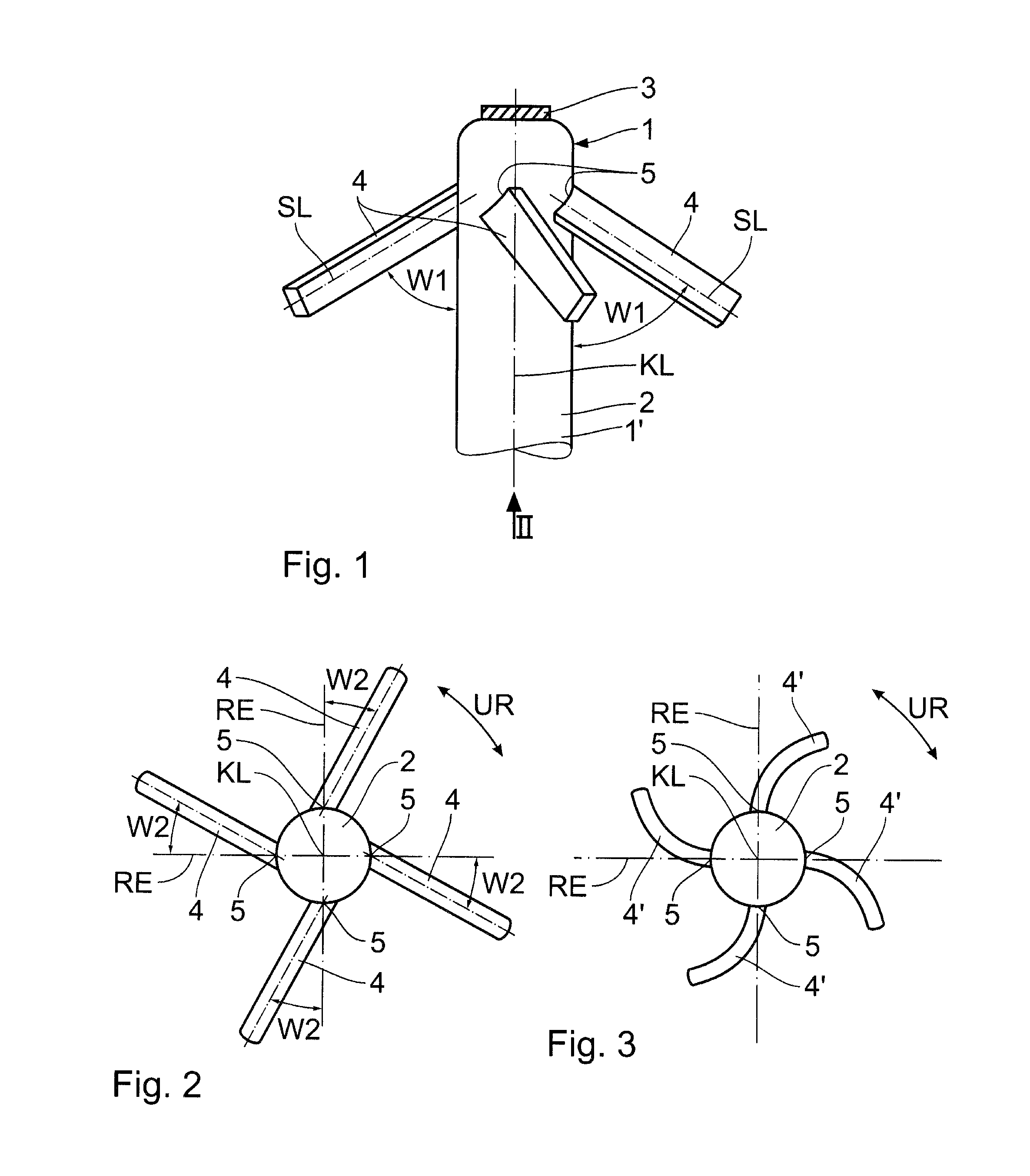
[0017]The two illustrations in FIGS. 1 and 2 show the distal end of 1 of an electrode body 2 of a cardiac catheter which is to be anchored in the trabeculae in the ventricle of the heart, for example. A cardiological potential may be measured and / or a voltage pulse may be delivered via the tip electrode 3 shown in FIG. 1, for example, if the cardiac catheter is used with a cardiac pacemaker.

[0018]To anchor the distal end 1 having its tip electrode 3, laterally projecting anchoring struts distributed around the circumference, which are made of an elastic plastic material—such as silicone—are injection molded directly onto the electrode body 2 before the end. These anchoring struts 4 project with their longitudinal axis SL at an acute angle W1, of 60 degrees for example, opening in the direction of the proximal end (approximated at 1′) to the body longitudinal axis KL of the electrode body 2. As may be seen in FIG. 1 and more clearly in FIG. 2, the four anchoring struts 4 are addition...


PUM


Abstract

A medical, implantable electrode device, in particular a cardiological electrode device, comprises an elongate electrode body (2) having a proximal and a distal end (1) for insertion into the body of the patient and multiple strut-like anchoring elements (4), which are attached laterally to the electrode body (2) before the distal end (1) for fixing the electrode device in the patient and are distributed around the circumference, which each project having their longitudinal axis (SL) at an acute angle (W1) opening in the direction of the proximal end in relation to the electrode body axis (KL). The anchoring elements have a preferred direction around the circumference in such a way that upon engagement of the anchoring elements (4) in a body part of the patient, a rotation of the electrode body (2) is opposed by a greater resistance in one rotational direction than in the opposite direction.

Description

FIELD OF THE INVENTION[0001]The present invention relates to a medical, implantable electrode device and particularly a cardiological electrode device such as a cardiac catheter.BACKGROUND OF THE INVENTION[0002]In the field of cardiac electrodes, it is typical to attach anchoring elements, which are used for fixing the electrode device in the body of the patient, laterally to the electrode, distributed around its circumference in the area of the distal end of the elongate electrode body, which is inserted into the patient body. These anchoring elements are wing-like struts made of soft plastic which are injection molded onto the electrode body, which hook in the trabeculae of the ventricle and are thus to ensure fixing of the electrode body. These anchoring elements, generally referred to as “tines”, each have their longitudinal axis projecting from the electrode body axis at an angle opening in the direction of the proximal end of the electrode body, in order to counteract withdraw...

Claims


Application Information

Patent Timeline
Patent Type & Authority Patents(United States)
IPC IPC(8): A61N1/05
CPCA61N1/057A61N2001/0585
Inventor KOLBERG, GERNOT
Owner BIOTRONIK SE & CO KG
Why Eureka
Try Eureka