Contact lens case drying and storage rack assembly

a technology for drying racks and contact lenses, which is applied in the field of drying and storing contact lens storage cases, can solve the problems of painful eye infections, and contact lens case components falling to the floor or into the sink

a technology for drying racks and contact lenses, which is applied in the field of drying and storing contact lens storage cases, can solve the problems of painful eye infections, and contact lens case components falling to the floor or into the sink

US20120042533A1Inactive Publication Date: 2012-02-23EVANS KAREN MARIE

Image

  • Contact lens case drying and storage rack assembly
  • Contact lens case drying and storage rack assembly
  • Contact lens case drying and storage rack assembly

Examples


Embodiment Construction

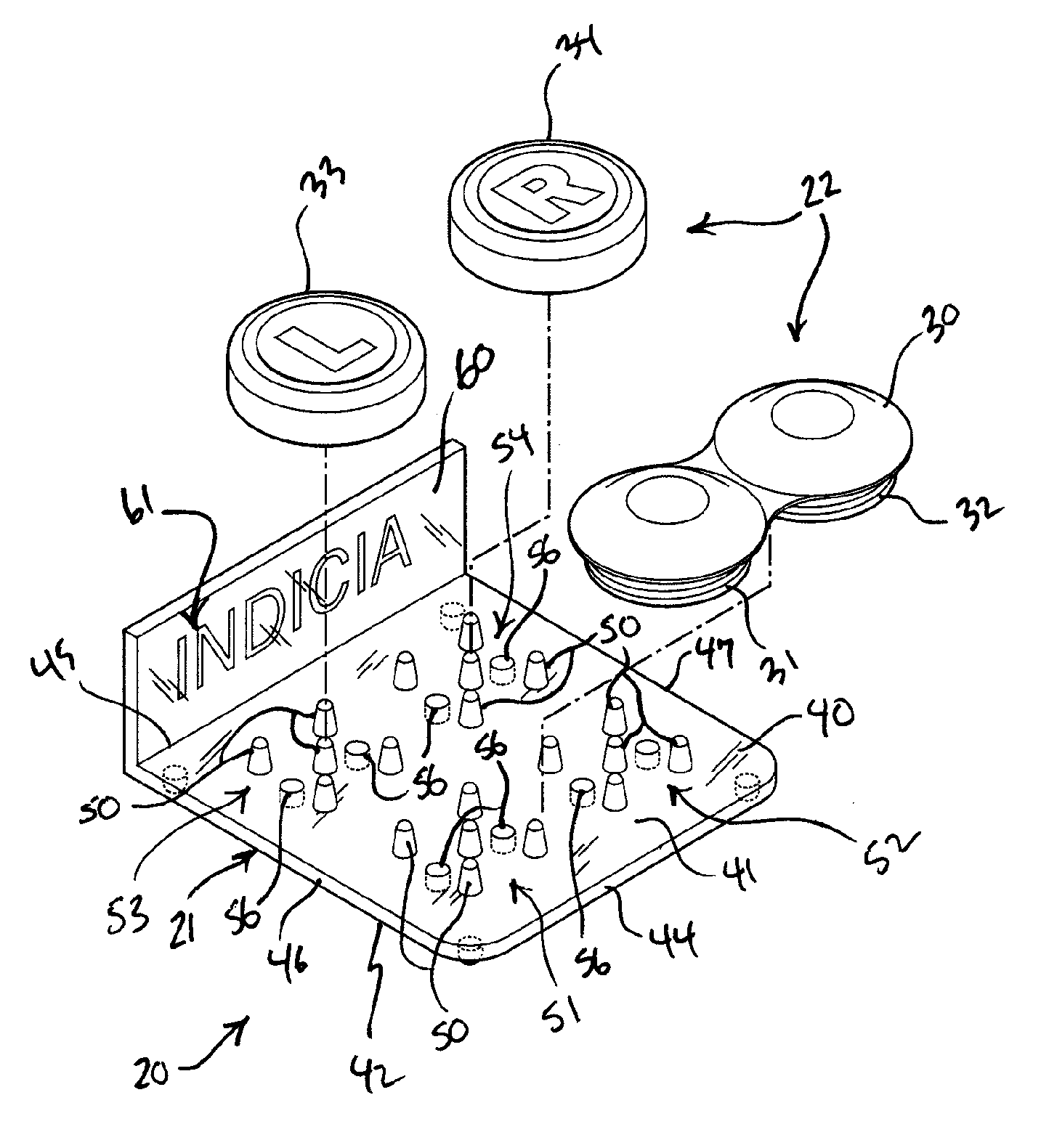
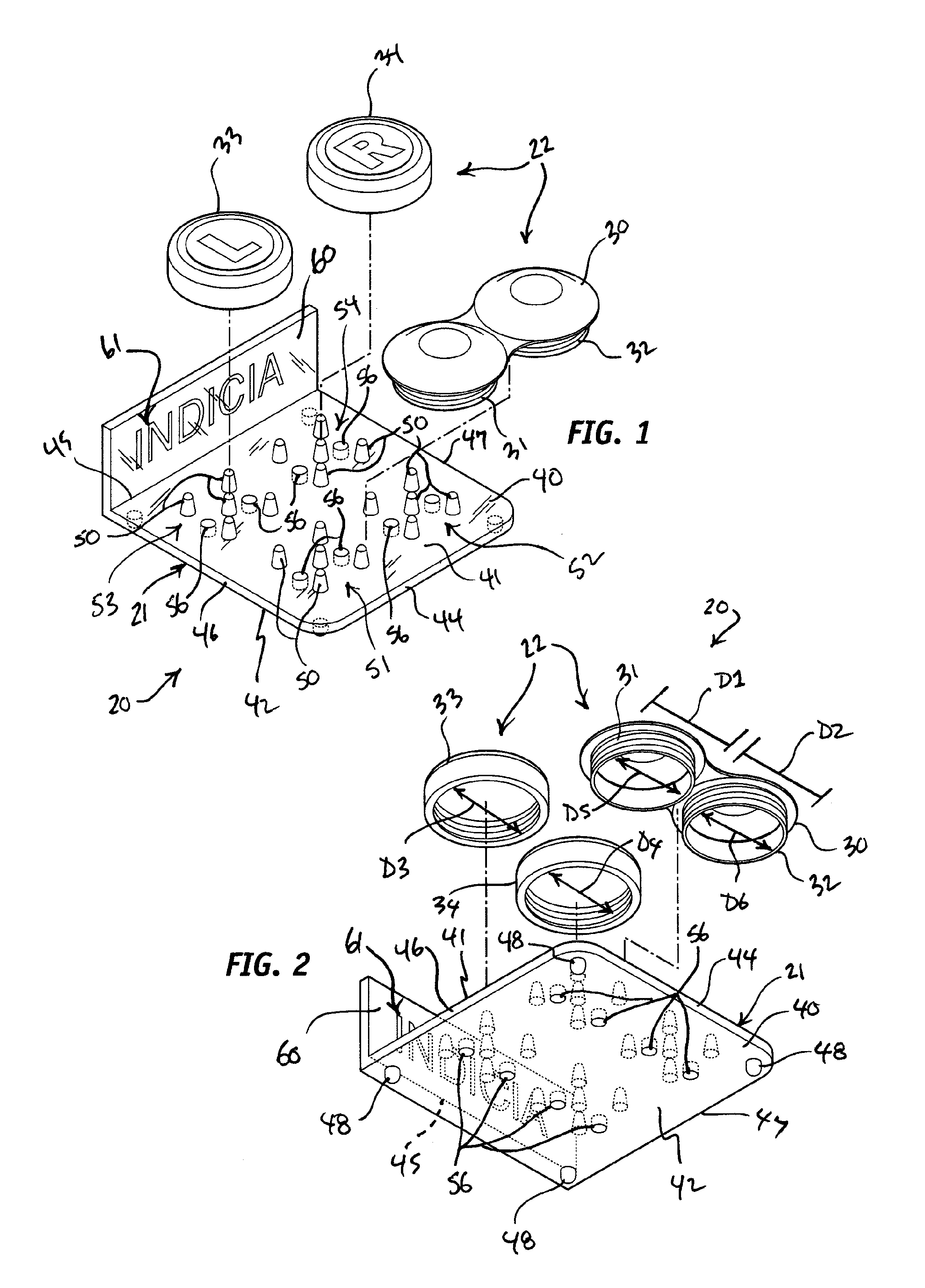
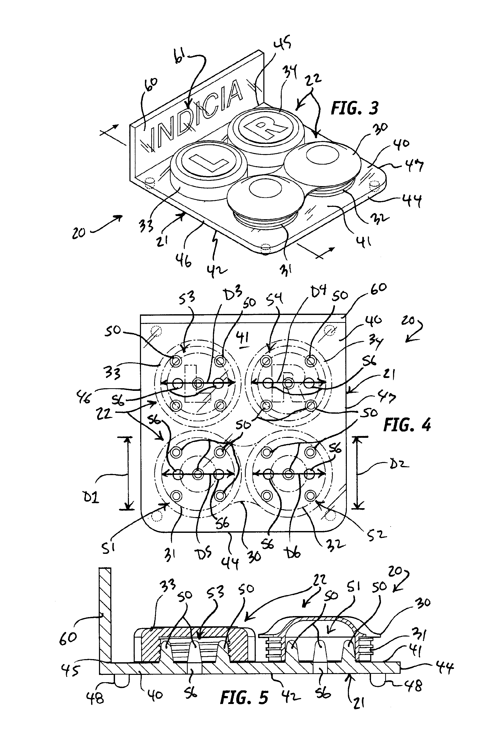
[0022]Turning now to the drawings, in which like reference characters indicate corresponding elements throughout the several views, attention is first directed to FIGS. 1 and 2 illustrating a drying rack and contact lens storage case assembly 20 including a drying frame denoted generally at 21, and a contact lens storage case assembly denoted generally at 22. Contact lens storage case assembly 21 is standard, common, and well known, and consists of a conventionally formed base 30, formed opposed, spaced-apart receptacles 31 and 32, and a pair of conventionally formed lids or caps 33 and 34 relating to receptacles 31 and 32, respectively. Base 30 and caps 33 and 34 are each integrally formed of plastic as is the case with standard contact lens storage case assemblies, such as assembly 22. Receptacles 31 and 32 are externally threaded, and caps 33 and 34 are internally threaded. In particular, receptacles 31 and 32 have outer diameters D1 and D2, respectively, which are externally thr...


PUM


Abstract

A drying rack and contact lens storage case assembly consists of a contact lens storage case assembly that includes a base formed with externally threaded receptacles having inner diameters, and internally threaded caps having inner diameters and which relate to the respective receptacles. A drying frame is formed with patterns of protuberances relating to inner diameters of the receptacles formed in the base and the caps, respectively. The receptacles are concurrently positionable on and over an opposed pair of the patterns of protuberances, and the caps are concurrently positionable on and over another opposed pair of the patterns of protuberances. There is at least one ventilation opening formed in the drying frame within each of the patterns of protuberances to provide drying ventilation.

Description

FIELD OF THE INVENTION[0001]The present invention relates to contact lens cases and covers and, more particularly, to systems and methods of drying and storing contact lens storage cases.BACKGROUND OF THE INVENTION[0002]Most contact lens wearers understand the importance of cleaning their contacts or contact lenses on a daily basis. Cleaning and disinfecting contacts on a daily basis extends the life of the contacts and reduces the risk of developing a potentially dangerous eye infection. A contact lens case, which is the “home” of the lenses during periods of nonuse, such as overnight, should be thought of as an extension of the contact lens, and should also be thoroughly cleaned on a regular basis.[0003]Contacts lens cases can be a significant source of microbial contamination. To help prevent eye infections, contact lens cases should be cleaned, rinsed and properly dried every day, particularly after the contacts are removed from the case and placed in the eyes for the day.[0004]...

Claims


Application Information

Patent Timeline
23 Feb 2012
Publication
US20120042533A1
IPC
F26B25/18; A45C11/04
CPC
A45C11/005; F26B25/185; F26B9/10; F26B9/003
Inventors
EVANS, KAREN MARIE