
Method and apparatus for performing an in-painting process on an image

a technology of in-painting and image, applied in the field of image processing system, can solve the problems of insufficient label optimality, inability to efficiently and accurately identify the best label, and damage to images or missing parts,

Inactive Publication Date: 2012-02-23
SONY CORP
View PDF7 Cites 3 Cited by
  • Summary
  • Abstract
  • Description
  • Claims
  • Application Information

AI Technical Summary

Benefits of technology

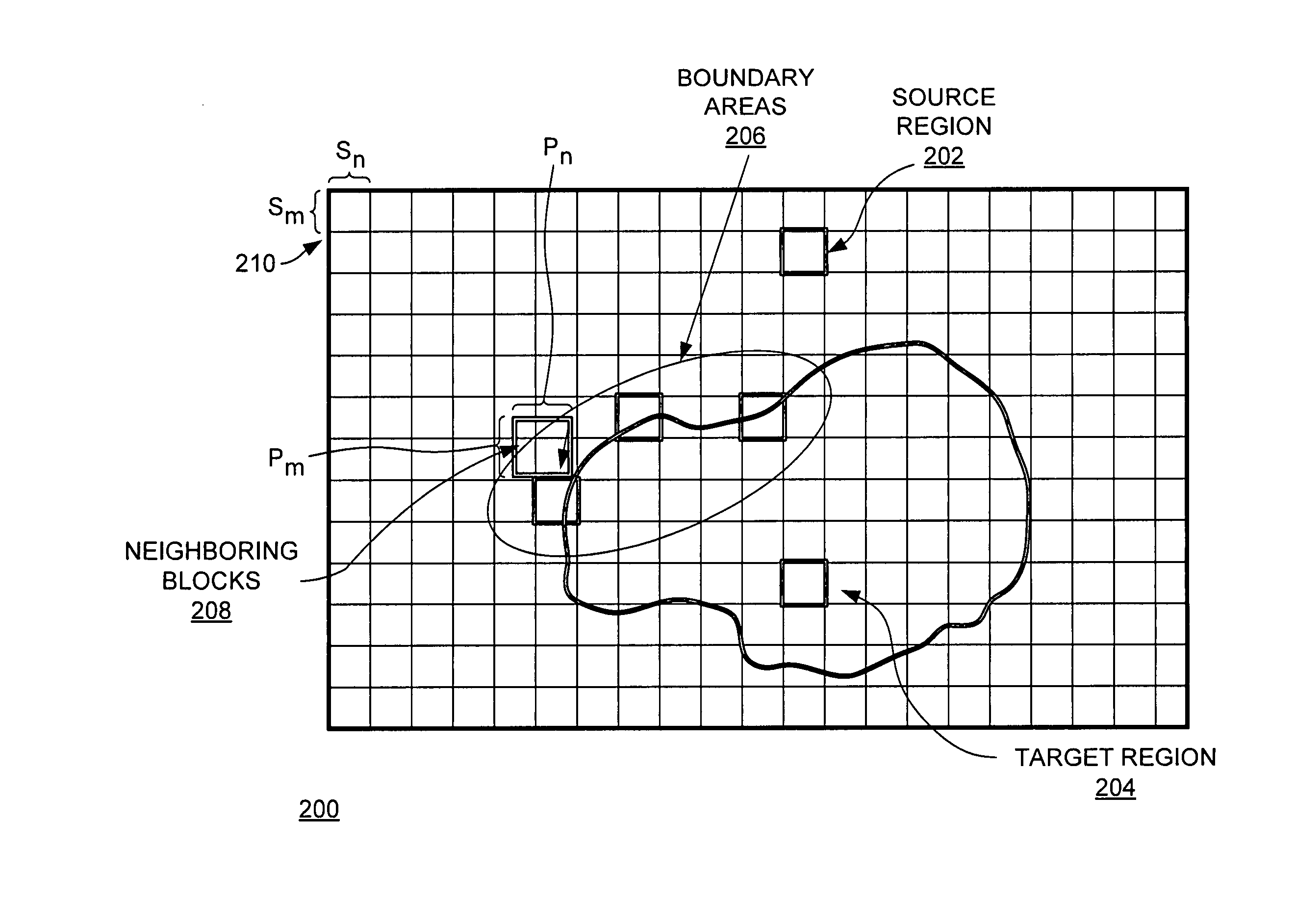
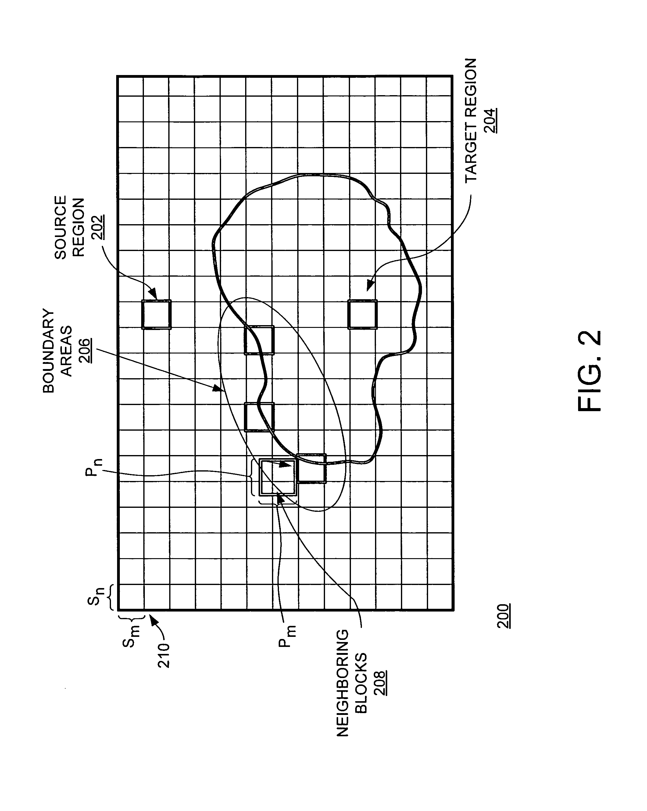
[0008]Various embodiments comprise a method and apparatus of in-painting an image using prioritized graph cut optimization. In one embodiment, the method includes examining an image comprising a plurality of pixels that form a source region and a target region, wherein the source region comprises pixel information partitioning the source region into blocks. The method further includes defining a plurality of boundary areas comprising a portion of the source region and a portion of the target region and examining a plurality of energy values fo

Problems solved by technology

These images may be damaged or include missing portions.
In other words, such techniques do not efficiently and accurately identify the best labels for multiple blocks to be in-painted during a single iteration.
While a label may be optimal for a certain block, the label is not optimal for the multiple blocks.
Accordingly, errors often result from performing the in-painting process on the block-by-block basis.
Erroneous labels are used in subsequent iterations resulting in propagation of the errors throughout the entire in-painting process.
As a result, typical in-painting processes operate very slowly and inefficiently.
Unfortunately, there are numerous potential labels for the pixels in the image.
Because of the large number of labels (intensity values), executing any of these optimization techniques requires significant processing power.
For example, implementing a graph-cut minimization technique for an image having more than two labels (for non-binary labeling in a non-binary image) is very complex and NP-hard (non-deterministic polynomial-time hard).

Method used


Image

  • Method and apparatus for performing an in-painting process on an image
  • Method and apparatus for performing an in-painting process on an image
  • Method and apparatus for performing an in-painting process on an image

Examples


example1

Example1:G{->i1,->i2}=∑j(->i1,j-->i2,j)2Example2:G{->i1,->i2}=(∑j(->i1,j-->i2,j)p)1 / p

[0043]At step 506, the method 500 examines smoothness costs between pairs of the neighboring blocks for each boundary area. In one embodiment, the smoothness cost for each pair of the neighboring blocks (xi and xj) associated with the boundary area is computed as:

E2(xi,xj)=∑di∈[Pm2-sm,Pm2]×[-Pn2,Pn2]di∈[1,sm]×[-Pn2,Pn2](Io(xi+di)-Io(xj+dj))2

[0044]Step 508 to step 512 represent an exemplary embodiment of the step 412 of the method 400. At step 508, the method 500 assigns initial intensity values for the boundary areas. In some embodiment, the image processing software assigns initial intensity values onto the source region, the boundary areas and / or the target region. These values may be assigned to homogenous blocks (i.e., nodes) of pixels (e.g., a block of eight by eight pixels). In the target region, nodes are initialized using intensity values of proximate neighboring blocks because the smoothnes...


PUM


Abstract

A method and apparatus of in-painting an image using prioritized graph cut optimization is disclosed. In one embodiment, the method includes examining an image comprising a plurality of pixels that form a source region and a target region, wherein the source region comprises pixel information partitioning the source region into blocks, defining boundary areas comprising a portion of the source region and a portion of the target region, computing a plurality of energy values for the source region and the boundary areas, wherein energy values represent intensity comparisons between the boundary areas and neighboring blocks of the source region and assigning labels to the boundary areas using on a graph-cut technique, wherein each label is associated with a neighboring block and an minimal energy value for each boundary area and storing pixel information based on the pixel information of the neighboring blocks associated with the minimal energy values.

Description

BACKGROUND[0001]1. Field of the Invention[0002]Embodiments of the present invention generally relate to an image processing system and, more particularly, to a method and apparatus for performing an in-painting process on an image using prioritized graph cut optimization.[0003]2. Description of the Related Art[0004]Conventional computer-based image processing systems utilize various computer-vision principles and techniques, such as patch (block)-based in-painting and exemplar-based in-painting processes, to restore and / or otherwise improve images. These images may be damaged or include missing portions. Accordingly, the image processing systems modify pixels to improve visual quality, restore damaged portions and replace any missing regions.[0005]These processes, however, are iterative solutions that divide an image into a plurality of blocks (e.g., eight×eight pixels, sixteen×sixteen pixels and the like) and operate on a block-by-block basis to perform in-painting. Basically, the ...

Claims


Application Information

Patent Timeline
IPC IPC(8): G06K9/34G06V10/426
CPCG06K9/469G06T2207/20072G06T5/005G06V10/426G06T5/77
Inventor BAE, SOO HYUNBAQAI, FARHAN
Owner SONY CORP
Learn More