Supercharge Your Innovation With Domain-Expert AI Agents!

Pick roller retraction method in a carriage printer

a carriage printer and retraction method technology, applied in the direction of printing, thin material processing, article separation, etc., can solve the problems of paper jamming, wrinkling or damaged recording medium, and requiring additional space and cos

Inactive Publication Date: 2012-03-01
EASTMAN KODAK CO
View PDF7 Cites 0 Cited by
  • Summary
  • Abstract
  • Description
  • Claims
  • Application Information

AI Technical Summary

Benefits of technology

[0010]These, and other, aspects and objects of the present invention will be better appreciated and understood when considered in conjunction with the following description and the accompanying drawings. It should be understood, however, that the following description, while indicating preferred embodiments of the present invention and numerous specific details thereof, is given by way of illustration and not of limitation. For example, the summary descriptions above are not meant to describe individual separate embodiments whose elements are not interchangeable. In fact, many of the elements des

Problems solved by technology

However, when only a few sheets of low stiffness are being loaded, the biasing force on the pick roller can result in wrinkled or damaged recording medium, which can lead to paper jams in some instances.
However, that paper feeding apparatus uses two motors and two one-way clutches, requiring additional space and cost.

Method used


Image

  • Pick roller retraction method in a carriage printer
  • Pick roller retraction method in a carriage printer
  • Pick roller retraction method in a carriage printer

Examples


Embodiment Construction

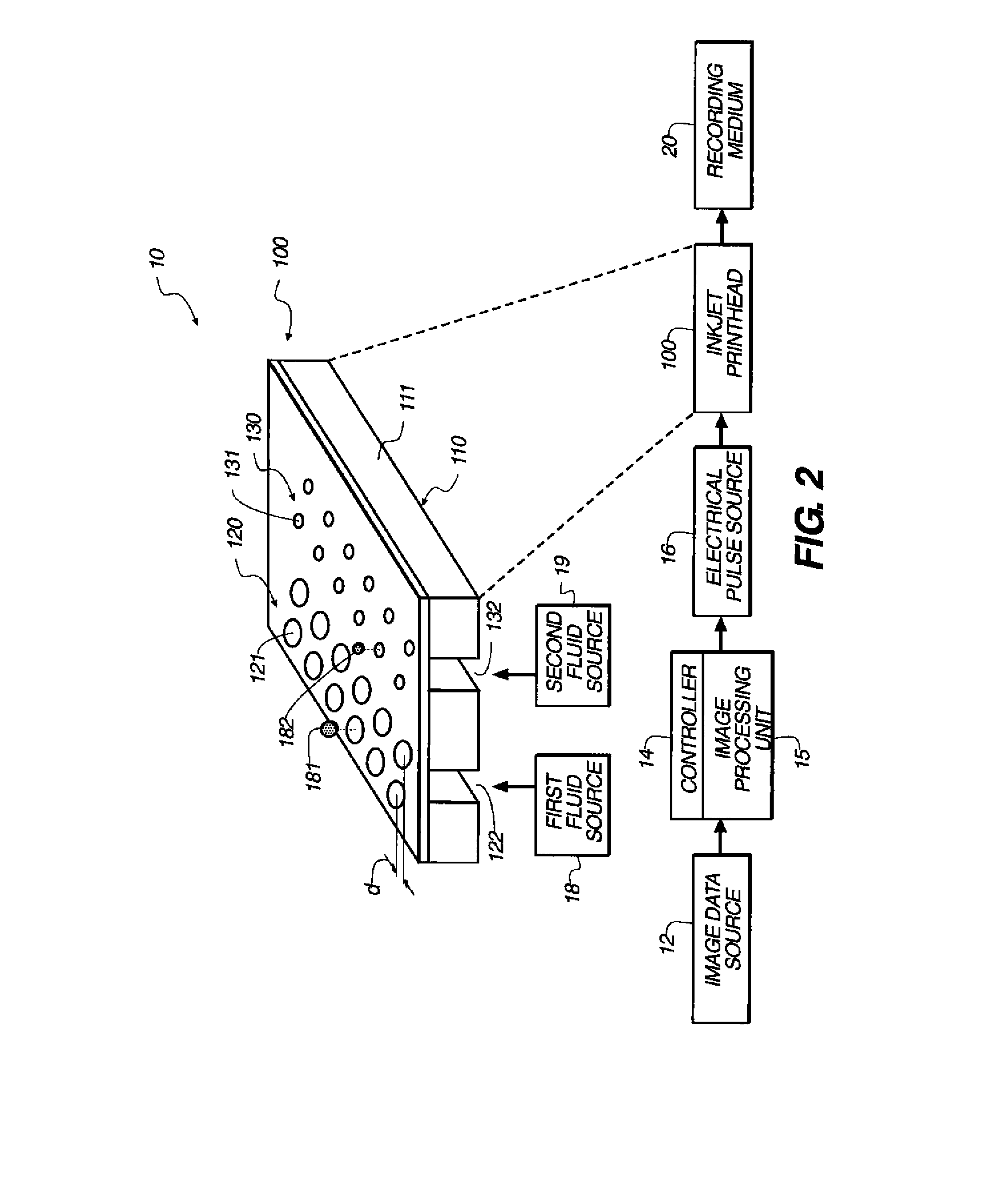
[0033]Referring to FIG. 2, a schematic representation of an inkjet printer system 10 is shown, for its usefulness with the present invention and is fully described in U.S. Pat. No. 7,350,902 which is incorporated by reference herein in its entirety. Inkjet printer system 10 includes an image data source 12, which provides data signals that are interpreted by a controller 14 as being commands to eject drops. Controller 14 includes an image processing unit 15 for rendering images for printing, and outputs signals to an electrical pulse source 16 of electrical energy pulses that are inputted to an inkjet printhead 100, which includes at least one inkjet printhead die 110.

[0034]In the example shown in FIG. 2, there are two nozzle arrays 120 and 130 that are each disposed along a nozzle array direction 254. Nozzles 121 in the first nozzle array 120 have a larger opening area than nozzles 131 in the second nozzle array 130. In this example, each of the two nozzle arrays has two staggered ...


PUM


Abstract

A method of automatically pivoting a pick arm assembly away from a media support in a printer by providing a printhead carriage with a sloped feature and providing a linking assembly coupled to the pick arm assembly with a ramped feature wherein pivoting the pick arm assembly away from the media support occurs when the printhead carriage travels along the carriage scan path.

Description

CROSS REFERENCE TO RELATED APPLICATIONS[0001]Reference is made to commonly assigned, co-pending U.S. patent applications:Ser. No. ______ by Wayne E. Stiehler and Sathiyamoorthy T. Sivanandam (Docket 96429) filed of even date herewith entitled “Media Stopper For A Printing System”;Ser. No. ______ by Wayne E. Stiehler and Sathiyamoorthy T. Sivanandam (Docket 96276) filed of even date herewith entitled “Pick Roller Retraction In A Carriage Printer”;Ser. No. ______ by Wayne E. Stiehler and Sathiyamoorthy T. Sivanandam (Docket 96535) filed of even date herewith entitled “Media Stopper Method For A Printing System”; andSer. No. ______ by Wayne E. Stiehler and Sathiyamoorthy T. Sivanandam (Docket 96540) filed of even date herewith entitled “Media Separator For A Printing System”, the disclosures of which are incorporated herein by reference in their entireties.FIELD OF THE INVENTION[0002]The present invention generally relates to paper handling in a carriage printer, and more particularly ...

Claims


Application Information

Patent Timeline
IPC IPC(8): B65H5/14B65H5/00B65H1/00
CPCB41J13/103B65H3/0661B65H3/0684B65H2403/513B65H2511/21B65H2801/12B65H2220/02B65H2220/08B65H2220/11
Inventor STIEHLER, WAYNE E.SATHIYAMOORTHY, SIVANANDAM T.
Owner EASTMAN KODAK CO
Features
  • R&D
  • Intellectual Property
  • Life Sciences
  • Materials
  • Tech Scout
  • Unparalleled Data Quality
  • Higher Quality Content
  • 60% Fewer Hallucinations
Learn More