
3D building generalization for digital map applications

a technology of 3d building and digital map, applied in the field of digital maps, can solve the problems of reducing visual details, unable to justify processing resources and time required to generate views, and presenting formidable technical limitations and/or cost factors

Inactive Publication Date: 2012-03-01
KANNENBERG OLIVER
View PDF5 Cites 29 Cited by
  • Summary
  • Abstract
  • Description
  • Claims
  • Application Information

AI Technical Summary

Problems solved by technology

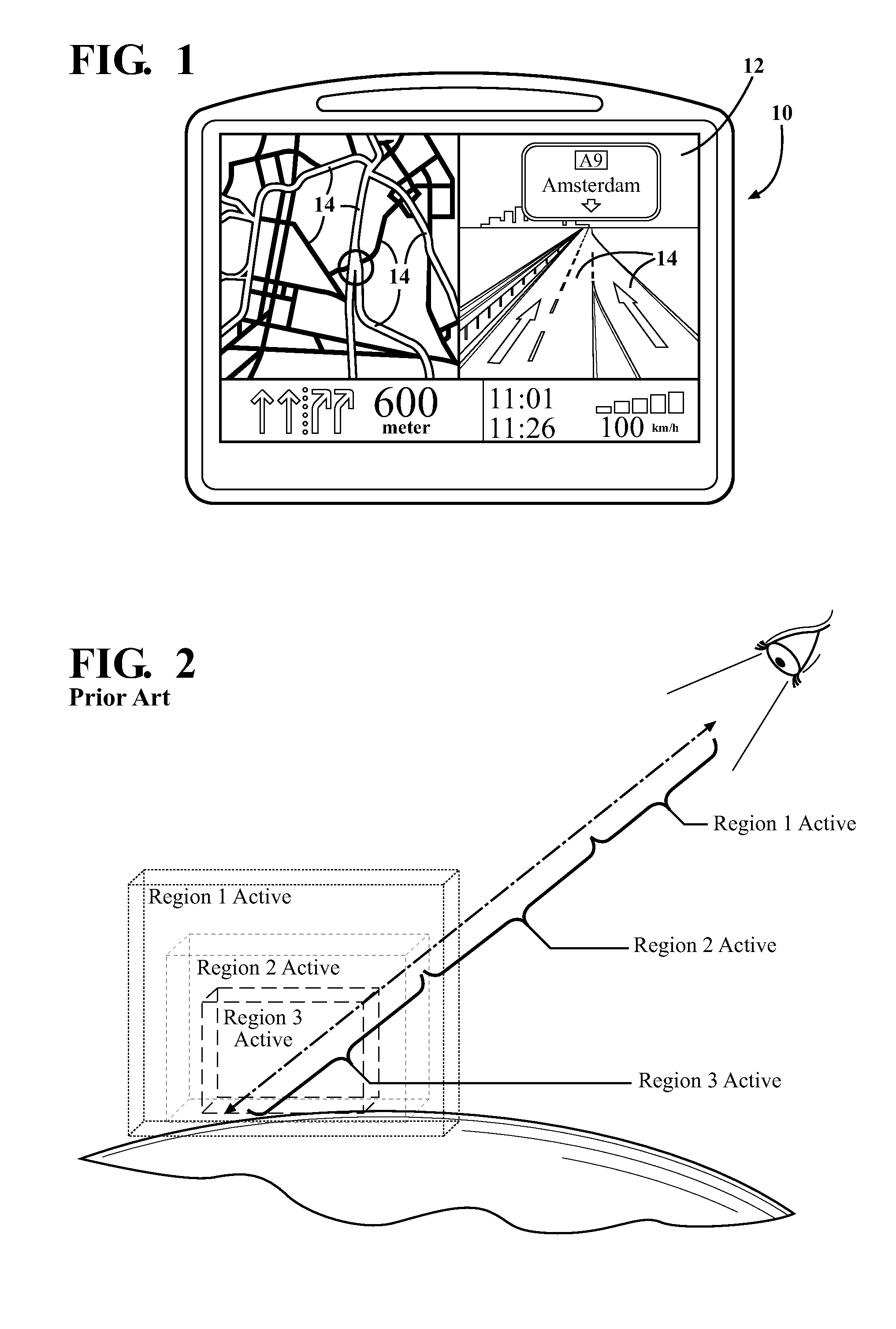
Because a navigation device display screen 12 has a limited amount of space, however, it is most efficient to construct the underlying software programs and functionality so that large amounts of data are loaded only when there are enough pixels to display the data adequately.
Although the use of Regions with an associated LoD provide benefits in terms of efficient utilization of computer processing power, they have still many drawbacks particularly in the field of navigation and 3D model renderings, where it is important that the renderings simulate live, fluid motion rather than abrupt transitions and snapshots.
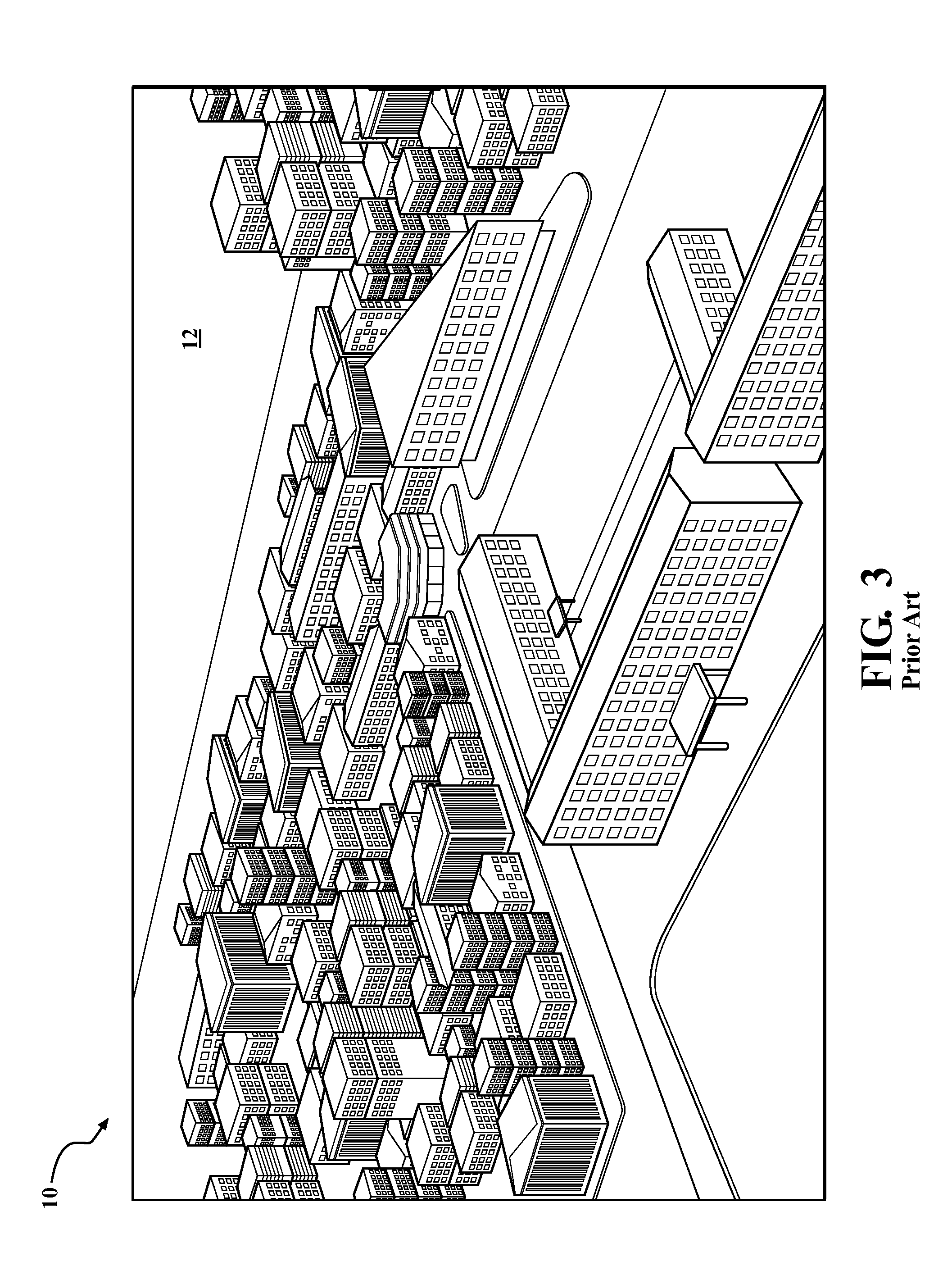
For purposes of navigation, an image like this provides more detail than is needed and can not justify the processing resources and time required to generate the view.
This is also quite unrealistic; in real life visual details diminish with distance.
Therefore, it is to be understood that when a personal navigation device 10 is required to display a large amount of 3D buildings or 3D structures, the available memory or power of the enabling computer presents a formidable technical limitation and / or cost factor.
These techniques, however, either fail to provide an optimal Level of Detail for navigation purposes or provide too much detail such that performance is wasted processing large amounts of unnecessary data that can slow or even overload the memory of the personal navigation device 10.
They also result in a non-realistic presentation of distant objects rendered with the same level of detail as near objects.

Method used


Image

  • 3D building generalization for digital map applications
  • 3D building generalization for digital map applications
  • 3D building generalization for digital map applications

Examples


Embodiment Construction

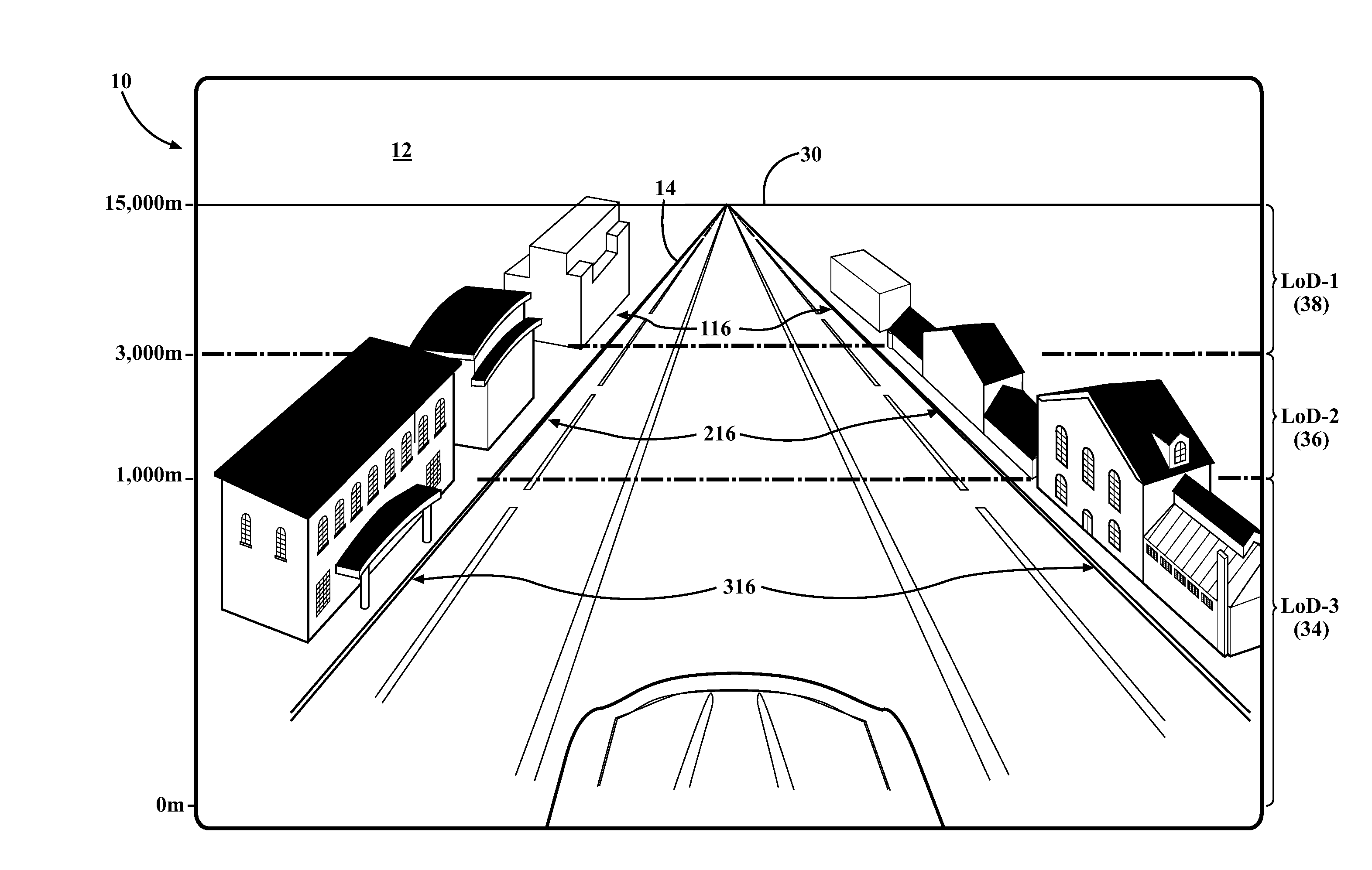
[0029]Referring to the figures, wherein like numerals indicate like or corresponding parts throughout the several views, this invention pertains to digital maps as used by navigation systems, as well as other map applications which may include those viewable through internet enabled computers, PDAs, cellular phones, and the like. 3D models can be rendered from numerous individual attributes which, when combined together, result in a highly detailed, realistic visual depiction of the physical object to which they correspond. However, these same 3D models can be rendered from fewer or different attributes which result in a less detailed visual depiction of the physical object, as compared with the full-attribute rendering. And still further, the same 3D models can be rendered with a minimum number or selection of attributes which result in a very basic, coarse visual depiction of the physical object. Generally, a 3D model rendered with fewer attributes requires less computing resource...


PUM


Abstract

A digital map application enables display of a large amount of 3D buildings or 3D structures to provide enhanced display and navigation features. The 3D models (116, 216, 316) are composed from a detailed set of attributes which, when combined, portray a highly detailed visual rendering of a physical object as it exists in real life. By selectively suppressing attributes, and in appropriate cases deriving new attributes from existing data, varying degrees of the 3D model (116, 216) can be represented in lower levels of detail with reduced processing resources and to achieve a more realistic depiction. The generalization of the 3D models can be structured as a function of the distance between the 3D model and an imaginary observer datum or other suitable reference point. In one embodiment, a plurality of contemporaneous rendering zones (34, 36, 38) are established so that a 3D model (116, 216, 316) is displayed with a particular combination or set of attributes depending which rendering zone (34, 36, 38) it is in.

Description

CROSS REFERENCE TO RELATED APPLICATIONS[0001]This application claims priority to U.S. Provisional Patent Application No. 61 / 202,585 filed Mar. 16, 2009, the entire disclosure of which is hereby incorporated by reference and relied upon.STATEMENT OF COPYRIGHTED MATERIAL[0002]A portion of the disclosure of this patent document contains material which is subject to copyright protection. The copyright owner has no objection to the facsimile reproduction by anyone of the patent document or the patent disclosure, as it appears in the official patent file or records, but otherwise reserves all copyright rights whatsoever.BACKGROUND OF THE INVENTION[0003]1. Field of the Invention[0004]This invention relates to digital maps, and more particularly toward a method for rendering three-dimensional models of real-life physical objects in a digital map.[0005]2. Related Art[0006]Personal navigation devices and / or map reading devices 10, like that shown for example in FIG. 1, are configured to utili...

Claims


Application Information

Patent Timeline
Patent Type & Authority Applications(United States)
IPC IPC(8): G06T15/00
CPCG09B29/10G01C21/32G09B29/003G01C21/206G01C21/3815G01C21/3841
Inventor KANNENBERG, OLIVER
Owner KANNENBERG OLIVER
Learn More