Power booster and electronic system using same

Inactive Publication Date: 2012-03-01
HON HAI PRECISION IND CO LTD
View PDF8 Cites 7 Cited by
  • Summary
  • Abstract
  • Description
  • Claims
  • Application Information

AI Technical Summary

Problems solved by technology

However, it is not uncommon that the current provided by the computer hosts to the USB interfaces is insufficient.
In this case, the computer hosts will cut off the power supply to the USB interfaces, which may cause data loss or / and damage the mobile hard disks.

Method used


Image

  • Power booster and electronic system using same
  • Power booster and electronic system using same

Examples


Embodiment Construction

[0008]Embodiments of the present disclosure will now be described in detail below and with reference to the drawing.

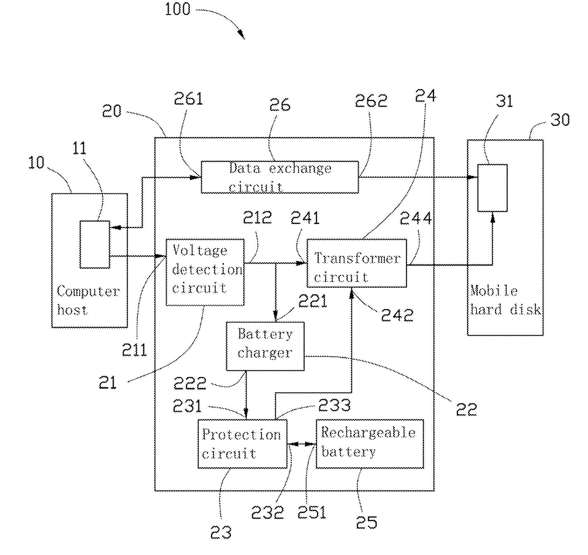
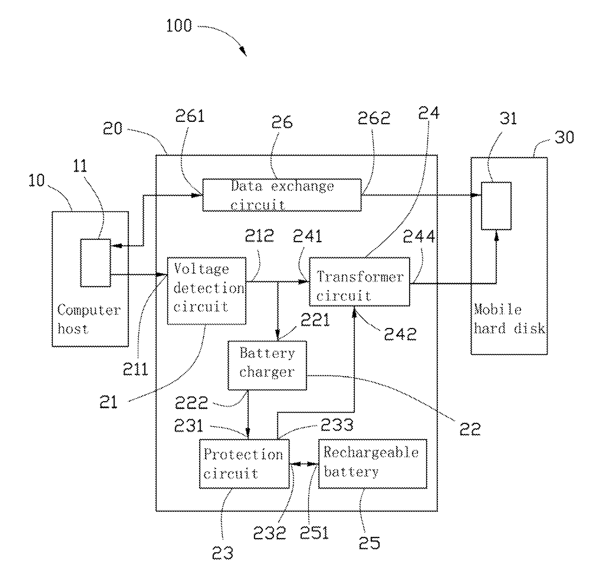
[0009]Referring to the drawing, an electronic system 100, according to an exemplary embodiment, includes a computer host 10 including a first USB interface 11, a mobile electronic device 30, and a power booster 20 electrically interconnected between the computer host 10 and the mobile electronic device 30 for providing a boosted power boosted by the power booster 20 to the mobile electronic device 30. In the present embodiment, the mobile electronic device 30 is a mobile hard disk and includes a second USB interface 31.

[0010]The power booster 20 includes a voltage detection circuit 21, a battery charger 22, a protection circuit 23, a transformer circuit 24, a rechargeable battery 25, and a data exchange circuit 26.

[0011]The voltage detection circuit 21 includes an input 211 and an output 212. The input 211 is connected to the first USB interface 111 of the computer hos...


PUM


Abstract

A power booster includes a voltage detection circuit, a battery charger, a rechargeable battery, and a transformer circuit. The voltage detection circuit detects a voltage of the input voltage of the power booster. An input of the battery charger is electrically connected to an output of the voltage detection circuit. The rechargeable battery includes an I / O port electrically connected to the battery charger. The transformer circuit includes a first voltage input, a second voltage input, and a voltage output. The first voltage input is electrically connected to the output of the voltage detection circuit. The second voltage input is electrically connected to the I / O port. The voltage output is used for connecting to a mobile electronic device.

Description

BACKGROUND[0001]1. Technical Field[0002]The disclosure relates to a power booster and an electronic system using the same.[0003]2. Description of Related Art[0004]Mobile hard disks are usually connected to USB interfaces of computer hosts by data lines to exchange data. When the mobile hard disks boot up, motor drivers of the mobile hard disks need a large current in short-term. However, it is not uncommon that the current provided by the computer hosts to the USB interfaces is insufficient. In this case, the computer hosts will cut off the power supply to the USB interfaces, which may cause data loss or / and damage the mobile hard disks.[0005]Therefore, it is desirable to provide a power booster and an electronic system using the same which can overcome the above problems.BRIEF DESCRIPTION OF THE DRAWING[0006]Many aspects of the present disclosure can be better understood with reference to the drawing. The components in the drawing are not necessarily drawn to scale, the emphasis in...

Claims


Application Information

Patent Timeline
IPC IPC(8): G06F1/26H02J3/32
CPCG06F1/266
Inventor KUNG, FAN-CHIN
Owner HON HAI PRECISION IND CO LTD
Why Eureka
Try Eureka