Walker with removable combined utility tray and seat

Inactive Publication Date: 2012-03-15
KIRBY AVERY
View PDF5 Cites 12 Cited by
  • Summary
  • Abstract
  • Description
  • Claims
  • Application Information

AI Technical Summary

Benefits of technology

[0010]Accordingly, it is an object of the present invention to provide a removable combined utility tray a

Problems solved by technology

This can be difficult for a person with limited dexterity.
Therefore, there is an unresolved conflict in the construction of such walkers.
It is clearly advantageous for the seat to be supported by the side braces, but the design goal of positioning the side braces to be as low as possible would normally result in the seat being too low to be comfortable and convenient for the user.
A low positioned seat, obviously, makes it difficult for the user to be able to sit and arise without difficulty.
Conventional solutions for pr

Method used


Image

  • Walker with removable combined utility tray and seat
  • Walker with removable combined utility tray and seat
  • Walker with removable combined utility tray and seat

Examples


Embodiment Construction

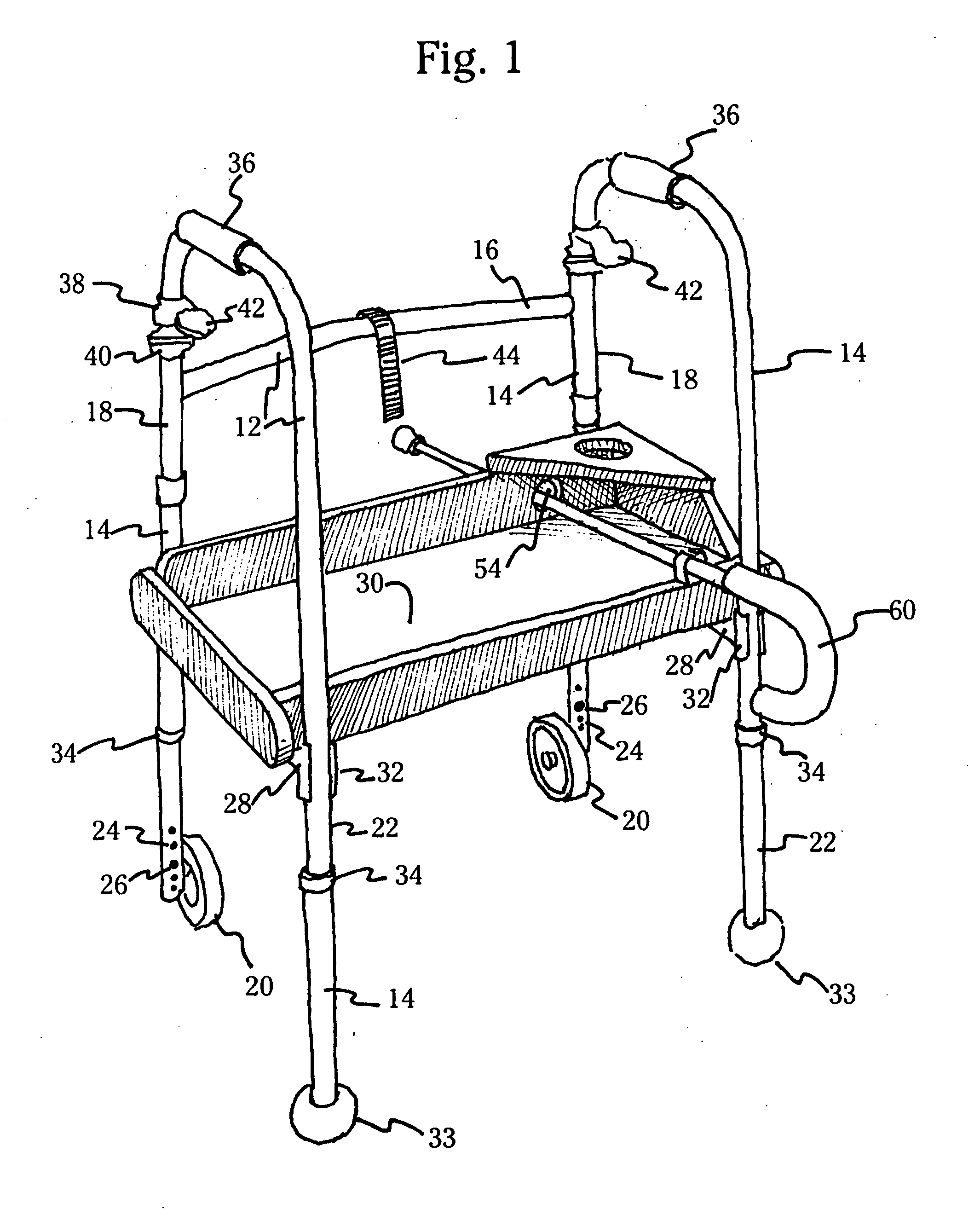
[0027]Referring now to FIG. 1 there is shown a perspective view of a walker 10 constructed in accordance with the present invention. The walker 10 includes a frame 12 comprising a pair of inverted U-shaped frame members 14 that are spaced apart to provide room for the user to stand when utilizing the apparatus and at least one crossbar 16 to maintain the frame members in an upright position. As employed herein, the front of the walker is the direction in which the user is ambulating when using the walker 10. Thus, in FIG. 1, the U-shaped frame members 14 are shaped so as to include front legs 18 that may have wheels 20 to facilitate movement of walker 10 by the user and rear legs 22. The rear legs terminate in a cushioned stop 33 which may be a tennis ball or the like. Both the front legs 18 and the rear legs 22 may be adjustable for height to suit the individual user. Such adjustable height means may be a plurality of holes 24 where a spring-loaded button 26 can emerge to lock the ...


PUM


Abstract

A walker with a tubular frame assembly has a pair of inverted U-shaped frame members each having a pair of legs. A front cross bar is attached to the frame members to maintain them in an upright position. A pair of side braces extend between the legs of the frame members. A combined tray-seat in a drawer shape is detachably mounted on the side braces. The side members of the tray-seat extend at least to the frame and side braces. Self-adhering strips on the front crossbar and tray-seat support the tray-seat vertically when the walker is moved. The tray-seat may have a hole in its front end and a broom clip on its rear end to support a cane. The hole also acts as a drain. A perforated platform on the combined tray-seat acts as a beverage holder.

Description

BACKGROUND OF THE INVENTION[0001]Typically, walkers are used by the elderly or invalid persons to assist in the ambulation process, that is, to enable such person to be able to walk certain distances on their own. Such walkers are quite common and, in general, most commonly have a pair of side frames, generally configured as A-shape or inverted U-shape and which are joined together with one or more cross-members so that the walker is sufficiently strong to support the person. The side frames include legs that extend downwardly to contact the ground for support of the walker as the person ambulates.[0002]Thus the upper portion of the side frames is a horizontal section that can be gripped by the user so that the walker can be used for the support as well as progressed forwardly by the user at each step. Preferably the overall unit can be formed of a tubular metal, such as aluminum, and the various components welded together to provide the necessary strength.[0003]One of the features ...

Claims


Application Information

Patent Timeline
IPC IPC(8): A61H3/00
CPCA61H3/04A61H2003/002A61H2201/1633A61H2201/0161A61H2003/004
Inventor KIRBY, AVERY
Owner KIRBY AVERY
Why Eureka
Try Eureka