Combination of device and retainer clip for retaining the device through an open window in panel

a technology of retainer clip and device, which is applied in the direction of coupling device connection, substation/switching arrangement details, incorrect coupling prevention, etc., can solve the problems of screwdriver drive, connector cannot be mounted to a panel without projection or groove, etc., to achieve the effect of convenient mounting and removal

Inactive Publication Date: 2005-03-15
JAPAN AVIATION ELECTRONICS IND LTD
View PDF9 Cites 6 Cited by
  • Summary
  • Abstract
  • Description
  • Claims
  • Application Information

AI Technical Summary

Benefits of technology

It is an object of this invention to provide a combination of an electrical device such as an electrical connector and a retaining clip by which a user can readily mount and remove the device through an open window in a panel.

Problems solved by technology

In order to mount or remove the connector to or from the panel, it is necessary to use a screwdriver and it is troublesome and time-consuming task to drive the screwdriver
However, the connector cannot be mounted to a panel having no projections or grooves corresponding to the connector having the grooves or projections.

Method used


Image

  • Combination of device and retainer clip for retaining the device through an open window in panel
  • Combination of device and retainer clip for retaining the device through an open window in panel
  • Combination of device and retainer clip for retaining the device through an open window in panel

Examples


Embodiment Construction

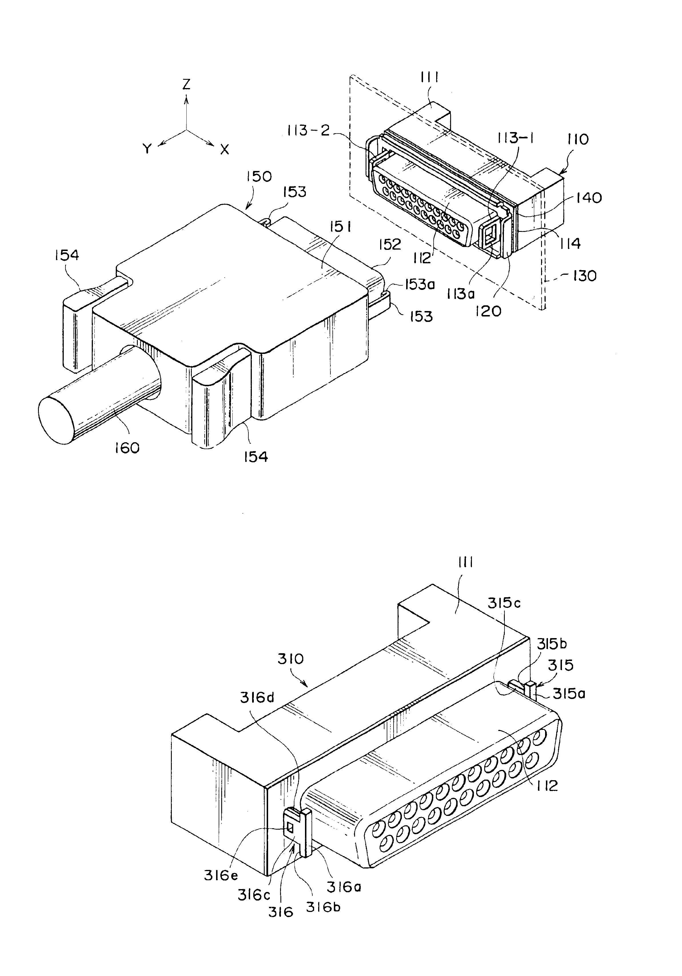
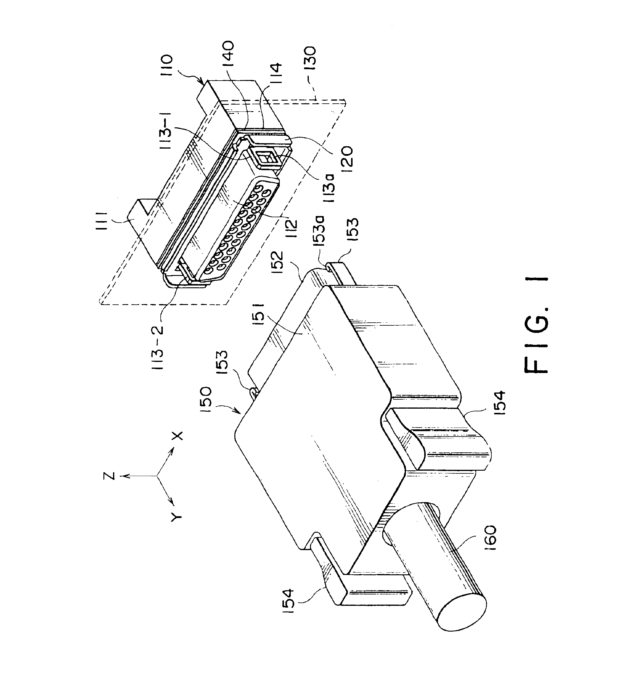
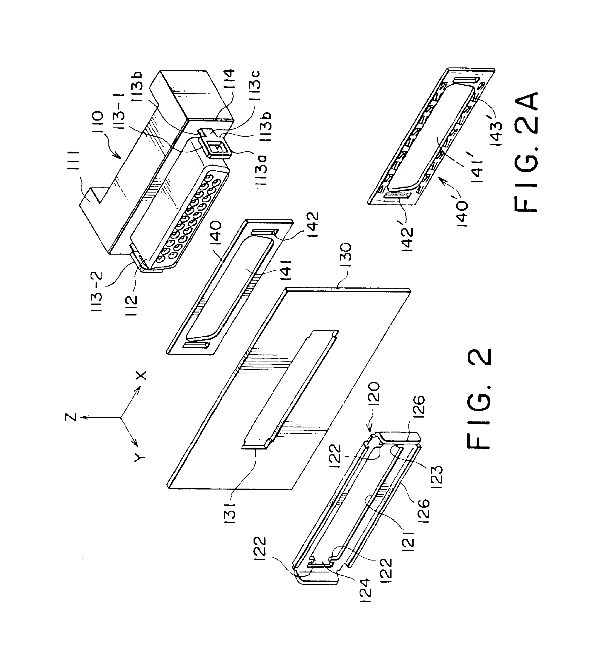
Referring to FIG. 1, an interface connector 110, which is connected to an electric circuit (not shown) in an apparatus, is usually on a panel 130 such as a housing wall panel of the apparatus through an open window formed in the panel 130. The connector 110 comprises a connector body 111 having a front surface, a connecting portion 112 projecting from the front surface frontward and two latching members 113-1 and 113-2 also projecting in parallel to the connecting portion 112 from the front surface at both sides of the connecting portion 112 opposite to each other in a first direction or X-direction. Two latching members 113-1 and 113-2 will often collectively be represented by the same reference numeral “113”. The connector 110 is usually provided with a metallic shell on the outer surface. The metallic shell is shown at 114. Each of the latching members 113 is provided with a latching hole 113a. A mating connector 150 is fixedly connected at an end of a cable 160 and is removably ...


PUM


Abstract

A retainer clip is used for retaining a connector through an open window in a panel. The connector has a connecting portion and two engaging elements projecting in a first direction together through the open window of the panel in a direction perpendicular to the first direction. The retainer clip has an aperture through which the connecting portion and the engaging elements are projected together in a first position and are slidable in the first direction to a second position. The clip is provided with locking tabs engaging with engaging surfaces on the engaging elements to prevent the clip from falling off from the connector in the second direction. The clip is further provided with stoppers engaging with detent surfaces formed on the engaging elements to prevent the clip from easily restore from the second position to the first position. In an embodiment, the clip is formed with elastic finger elements extending from side edge of the aperture thereof and stoppers are formed on the extending ends of the finger elements. The retainer clip can have, in place of the aperture, a cut-away portion with three sides closed but one side open.

Description

BACKGROUND OF THE INVENTIONThis invention relates to mounting technique of a device such as an electrical connector or others through an open window in a panel such as a panel wall of a housing of an electronic apparatus.In mounting an electrical connector through an open window in a panel, screws or bolts are usually used. A connecting portion is projected through the open window and screws are screwed into a connector body through the panel. The panel must often be formed with screw receiving holes adjacent the open window. In a connector having nuts fixedly mounted thereinto, bolts are driven into the nuts through the bolt-receiving holes formed in the panel.In order to mount or remove the connector to or from the panel, it is necessary to use a screwdriver and it is troublesome and time-consuming task to drive the screwdriverIn a different way, one of a connector and a panel is formed with projections and the other is formed with corresponding grooves or slits. The connector and...

Claims


Application Information

Patent Timeline
Patent Type & Authority Patents(United States)
IPC IPC(8): H01R13/74H01R13/641
CPCH01R13/741H01R13/641
Inventor MURAYAMA, RYUSUKE
Owner JAPAN AVIATION ELECTRONICS IND LTD
Why Eureka
Try Eureka