Lighting device, display device and television receiver
- Summary
- Abstract
- Description
- Claims
- Application Information
AI Technical Summary
Benefits of technology
Problems solved by technology
Method used
Image

Examples
first embodiment
[0041]The first embodiment of the present invention will be explained with reference to FIGS. 1 to 12.
[0042]First, a construction of a television receiver TV including a liquid crystal display device 10 will be explained.
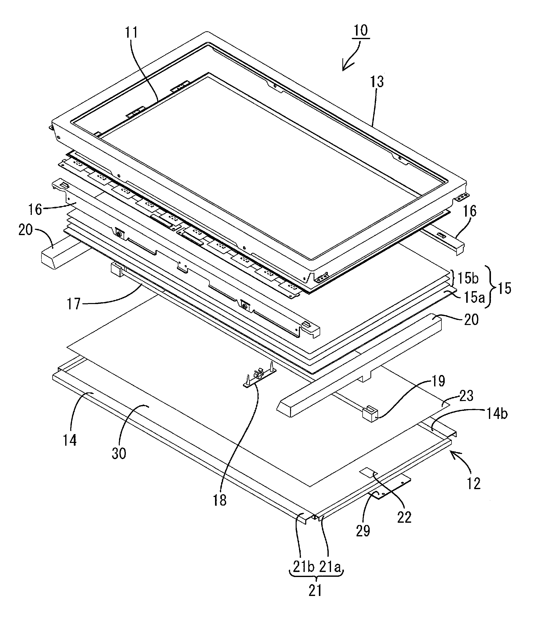
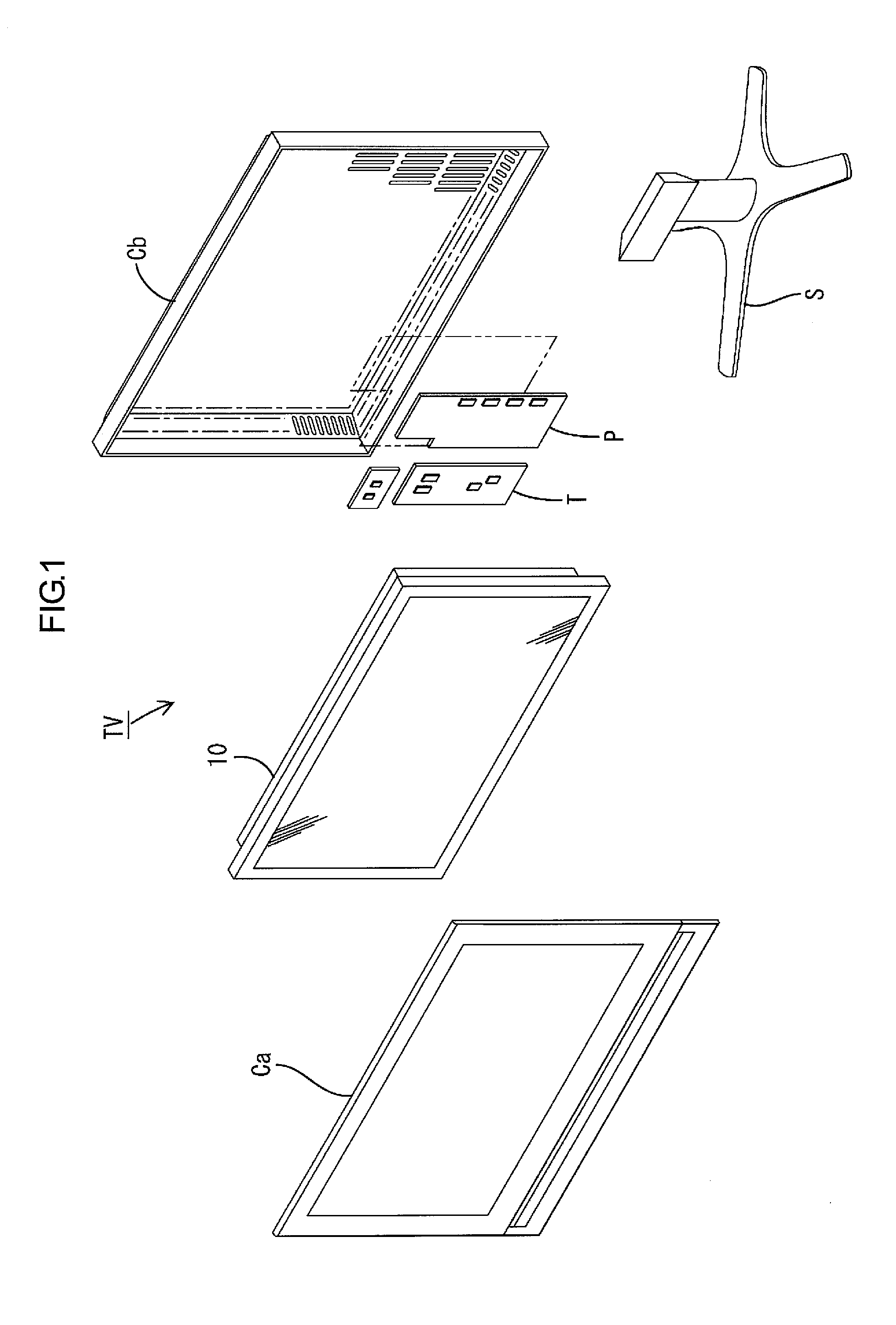
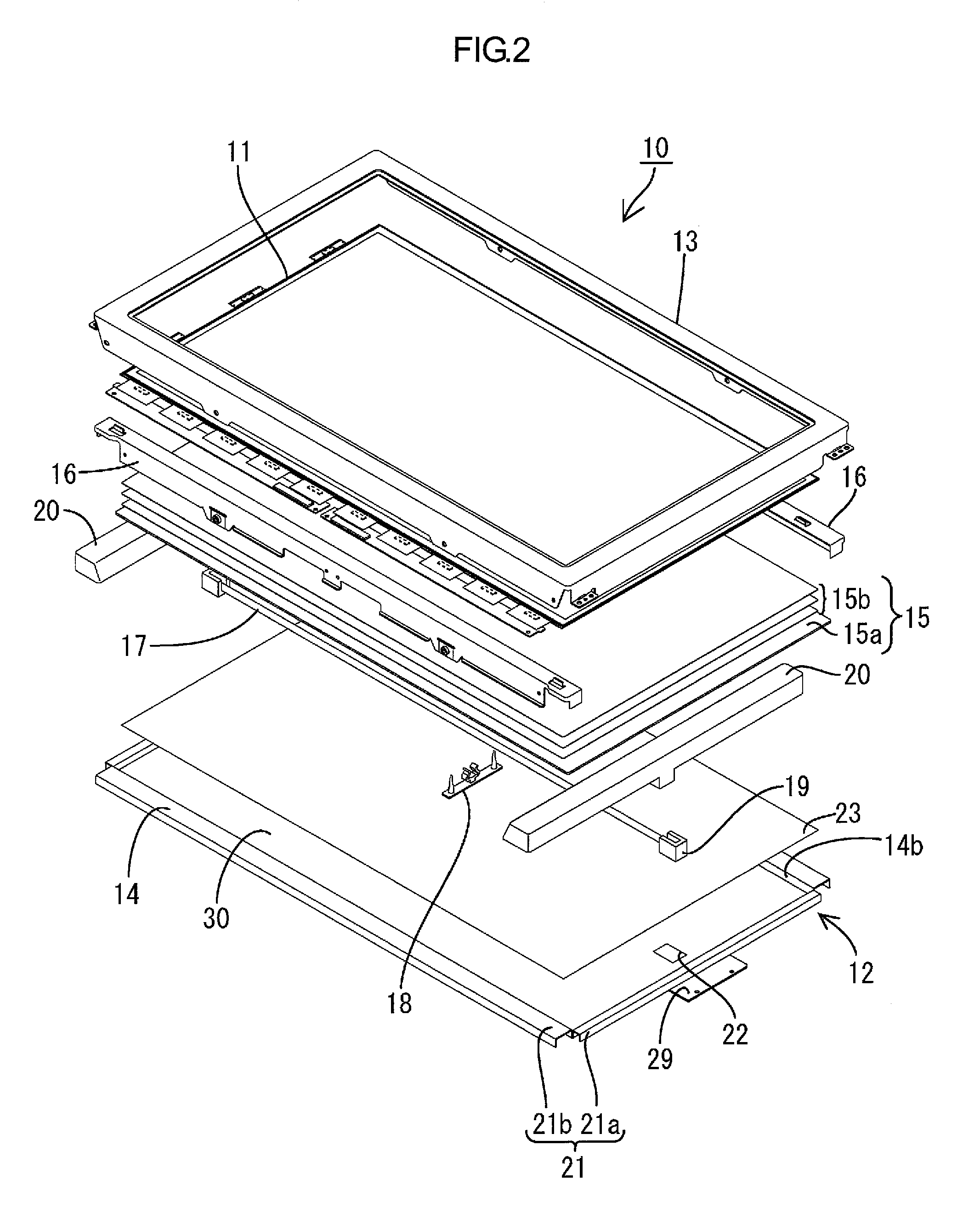
[0043]As illustrated in FIG. 1, the television receiver TV of the present embodiment includes the liquid crystal display device 10, front and rear cabinets Ca, Cb that house the liquid crystal display device 10 therebetween, a power source P, a tuner T and a stand S. An overall shape of the liquid crystal display device (display device) 10 is a landscape rectangular. The liquid crystal display device 10 is housed in a vertical position such that a short-side direction thereof matches a vertical line. As illustrated in FIG. 2, it includes a liquid crystal panel 11 as a display panel, and a backlight device 12 (lighting device), which is an external light source. They are integrally held by a frame-like bezel 13 and the like.
[0044]Next, the liquid crystal panel 11 and...
first modification
of First Embodiment
[0089]The light reflectance distribution of the diffuser 15a may be modified as illustrated in FIGS. 13 and 14. FIG. 13 is a plan view illustrating a light reflectance distribution of a surface of the diffuser in FIG. 13 that faces the hot cathode tube according to one modification. FIG. 14 is a graph illustrating a light reflectance change in the short-side direction of the diffuser in FIG. 13. In the following modification, the same components and parts as the first embodiment are indicated by the same symbols and will not be explained.
[0090]As illustrated in FIGS. 13 and 14, the light source overlapping portion DA of a diffuser 150a (a surface of the portion that overlaps the light source installation area LA facing the hot cathode tube 17) has the highest light reflectance, and in the empty area overlapping portion DN of the diffuser 150a (a surface of the portion that overlaps the empty area LN facing the hot cathode tube 17), the light reflectance decreases ...
second modification
of First Embodiment
[0094]In a second modification of the first embodiment, a color adjustment function is applied to portion is added to the light reflecting portion 50. The second modification will be explained with reference to FIGS. 15 to 18.
[0095]FIG. 15 is a plan view illustrating an arrangement pattern of the light reflecting portion formed on a surface of the diffuser that faces the hot cathode tube. FIG. 16 is a spectral plot of each color. FIG. 17 is a plan view explaining a distribution of color intensity of a surface of the diffuser that faces the hot cathode tube. FIG. 18 is a graph illustrating a color intensity change in the short-side direction of the diffuser in FIG. 17. In FIGS. 17 and 18, the long-side direction of the diffuser is referred to as an X-axis direction and the short-side direction thereof is referred to as a Y-axis direction. In FIG. 18, a horizontal axis shows the Y-axis direction (short-side direction) and the light reflectance is plotted on a graph ...
PUM
 Abstract
Description
Claims
Application Information
 - Generate Ideas
- Intellectual Property
- Life Sciences
- Materials
- Tech Scout
- Unparalleled Data Quality
- Higher Quality Content
- 60% Fewer Hallucinations
Browse by: Latest US Patents, China's latest patents, Technical Efficacy Thesaurus, Application Domain, Technology Topic, Popular Technical Reports.
© 2025 PatSnap. All rights reserved.Legal|Privacy policy|Modern Slavery Act Transparency Statement|Sitemap|About US| Contact US: help@patsnap.com