Method for manufacturing head including light source unit for thermal assist

a technology of thermal assist and manufacturing method, which is applied in the direction of manufacturing tools, mounting heads within the housing, instruments, etc., can solve the problems of significantly reducing the light use efficiency of the head, difficult to provide sufficient joining strength, and difficult to sufficiently increase the conformity between the joining surfaces of the light source uni

Active Publication Date: 2012-03-29
TDK CORPARATION
View PDF4 Cites 24 Cited by
  • Summary
  • Abstract
  • Description
  • Claims
  • Application Information

AI Technical Summary

Problems solved by technology

If the solder is too thin, it is difficult to provide sufficient joining strength.
On the other hand, if the solder is too thick, the distance between the light source unit and the slider will be so large that light emitted from the light source significantly attenuates before reaching an optical system in the slider, possibly resulting in a significantly reduced light use efficiency of the head.
However, it is difficult to sufficiently increase the conformity between the joining surfaces of the light source unit and the slider by this method of moving the light source.
In fact, the surfaces of the unit substrate of the light source unit have errors in squareness to each other due to working accuracy limitations.
In addition, the surfaces of the clamp that hold the light source unit also have errors and the movement of clamp with respect to the stage also has an error due to adjustment limitations.
Therefore, even when the clamp is moved closer to the stage to bring the light source unit into contact with the slider, it is significantly difficult to achieve high conformity between the joining surfaces of the light source unit and the slider.
If a conformity adjustment mechanism such as an air gimbal is provided in the stage in order to address the conformity problem, the mechanism, will have little effect in adjusting conformity because the size of the slider placed on the stage is very small.
The mechanism also adds complexity to the joining apparatus.

Method used


Image

  • Method for manufacturing head including light source unit for thermal assist
  • Method for manufacturing head including light source unit for thermal assist
  • Method for manufacturing head including light source unit for thermal assist

Examples


Embodiment Construction

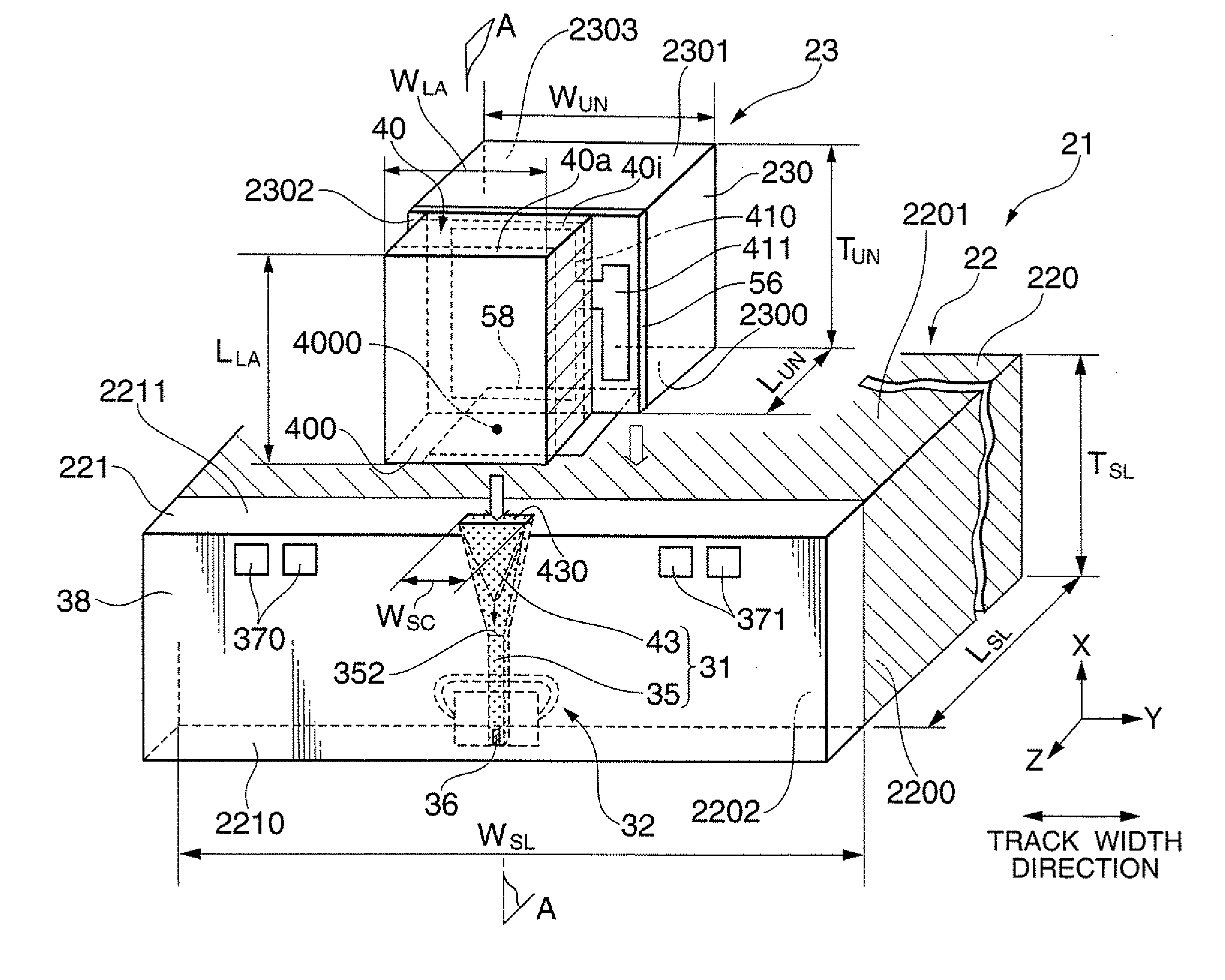
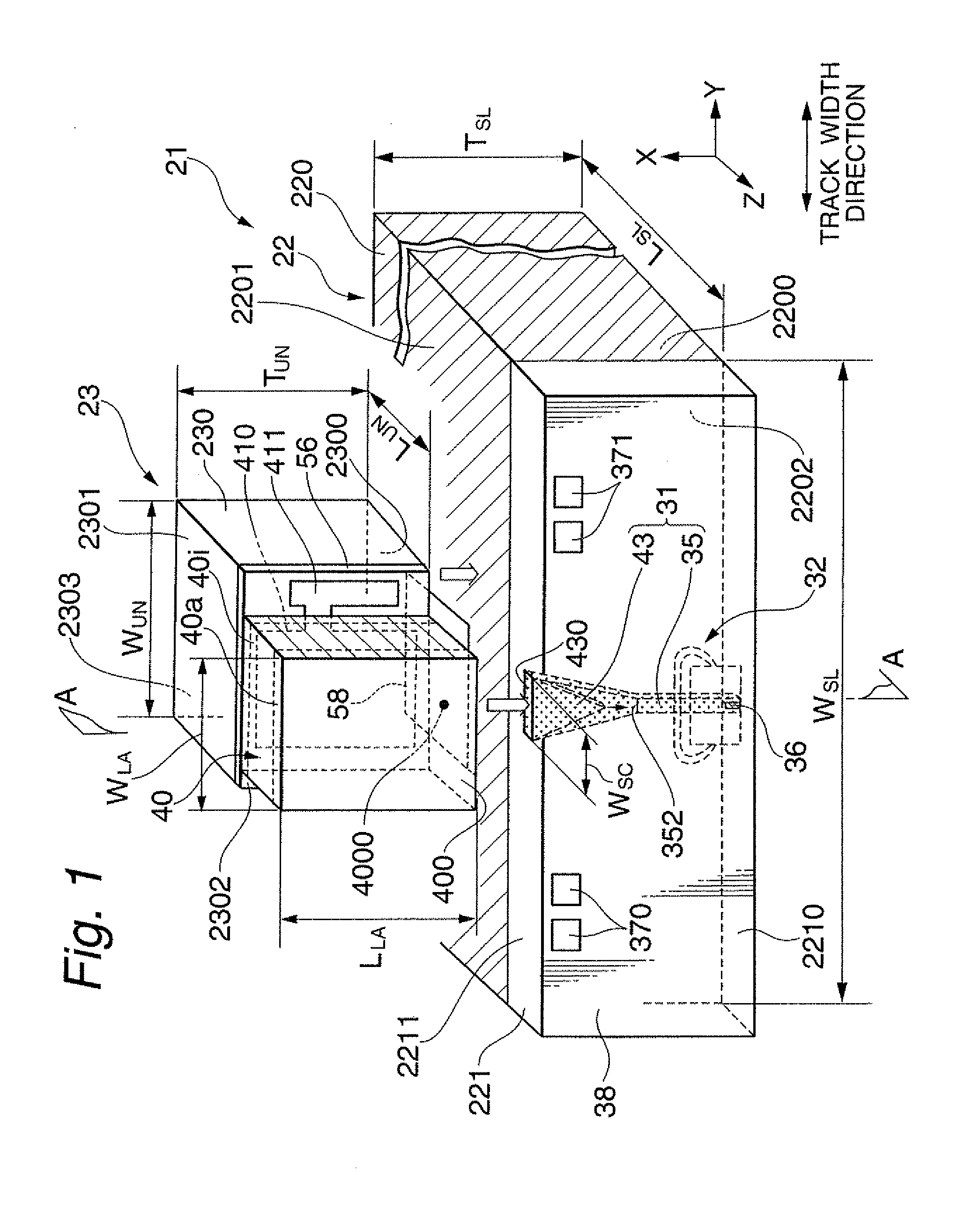
[0050]FIG. 1 shows a perspective view illustrating one embodiment of a thermally-assisted magnetic recording head manufactured by a manufacturing method according to the present invention.

[0051]As shown in FIG. 1, a thermally-assisted magnetic recording head 21 is fabricated by aligning and joining a light source unit 23, which includes a laser diode 40 as a light source for thermal assist, and a slider 22, which includes an optical system 31.

[0052]The slider 22 includes: a slider substrate 220 having an air bearing surface (ABS) 2200 processed so as to provide an appropriate flying height; and a head element part 221 that includes an optical system 31 and is formed on an element-integration surface 2202 that is perpendicular to and adjacent to the ABS 2200. While, the light source unit 23 includes: a unit substrate 230 having an joining surface 2300; and a laser diode 40 as a light source provided on a source-installation surface 2302 that is perpendicular to and adjacent to the jo...


PUM

PropertyMeasurementUnit
thicknessaaaaaaaaaa
distanceaaaaaaaaaa
angleaaaaaaaaaa

Abstract

Provided is a method for manufacturing a thermally-assisted magnetic recording head in which a light source unit including a light source and a slider including an optical system are joined. The method comprises steps of: adhering by suction the light source unit with a back holding jig; bringing the light source unit into contact with a slider back surface of the slider; applying a load to a load application surface of the light source unit by a loading means to bring a joining surface of the light source unit into conformity with the slider back surface; positioning the light source unit apart from the slider, and then aligning the light source with the optical system; bringing again the light source unit into contact with the slider; and applying a load again to the load application surface to bring the joining surface into conformity with the slider back surface. Thus, the conformity between them can be significantly increased, thereby achieving adequately strong junction and adequately high accuracy in position.

Description

BACKGROUND OF THE INVENTION[0001]1. Field of the Invention[0002]The present invention relates to a method for manufacturing a thermally-assisted magnetic recording head used for thermally-assisted magnetic recording in which a portion to be written of a magnetic recording medium is heated and thus writing is performed to the portion where anisotropic magnetic field decreases. The present invention especially relates to a method for manufacturing a thermally-assisted magnetic recording head constituted by joining a light source unit and a slider. The present invention further relates to a apparatus used for the joining.[0003]2. Description of the Related Art[0004]With the explosion in the use of the Internet in these years, a huge amount of data that are incommensurably larger than ever are stored and used on computers such as servers and information processing terminals. This trend is expected to further grow at an accelerated rate. Under these circumstances, demand for magnetic ...

Claims


Application Information

Patent Timeline
Patent Type & Authority Applications(United States)
IPC IPC(8): G11B5/127G11B7/22
CPCG11B5/105G11B5/314G11B5/6088G11B2005/0021Y10T428/1193Y10T29/53265Y10T29/49048Y10T29/53165Y10T29/49044Y10T29/49046Y10T428/1143Y10T29/49032Y10T428/1171Y10T29/49052
Inventor SHIMAZAWA, KOJITAKAYAMA, SEIICHIMORI, NOBUYUKITSUCHIYA, YOSHIHIROHARA, SHINJI
Owner TDK CORPARATION
Why Eureka
Try Eureka