Signal detection circuit, method and system

Active Publication Date: 2012-04-05
HUAWEI TECH CO LTD
View PDF2 Cites 6 Cited by
  • Summary
  • Abstract
  • Description
  • Claims
  • Application Information

AI Technical Summary

Benefits of technology

[0015]In the circuit, the method, and the system for signal detection provided in the embodiments of the present invention, through this embodiment of the present invention, the signal conversion module converts the reference voltage signal into the reference current signal and converts the voltage signal to be detected into the current signal to be detected; the threshold control module may receive the threshold control signal, changes the magnitude of the threshold current signal according to the threshold control signal, and sends the threshold current signal to the comparison module. In this way, the threshold of the signal detection circuit may be configured flexibly, so that detection flexibility of the signal detection circuit is improved. Furthermore, in the embodiments of the present invention, the signal detection circuit is integrated into a PHY chip through an integrated circuit technology, so that the setting-up cost is reduced in comparison with the prior art.

Problems solved by technology

In the prior art, a signal detection circuit is generally implemented by adopting separate devices, so that the cost for setting up a whole signal detection circuit is high.
Furthermore, a single threshold of a comparator adopted by the conventional signal detection circuit is set, and therefore, detection flexibility of the whole signal detection circuit is poor.

Method used


Image

  • Signal detection circuit, method and system
  • Signal detection circuit, method and system
  • Signal detection circuit, method and system

Examples


Embodiment Construction

[0029]A signal detection circuit provided in the present invention is described in detail in the following with reference to specific embodiments and accompanying drawings.

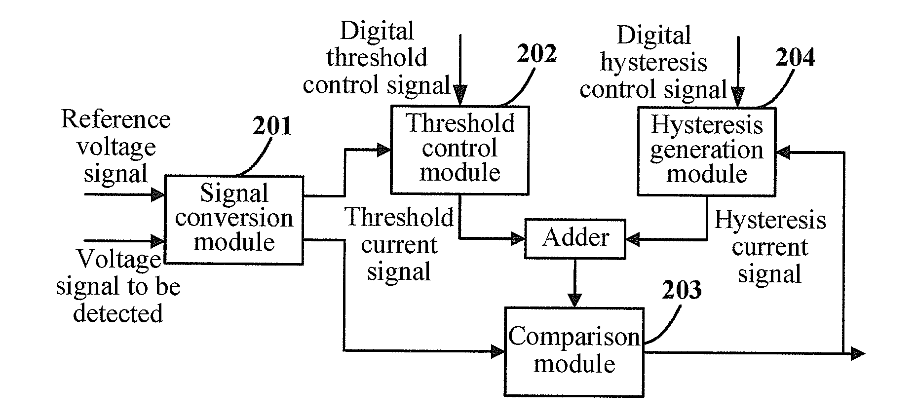
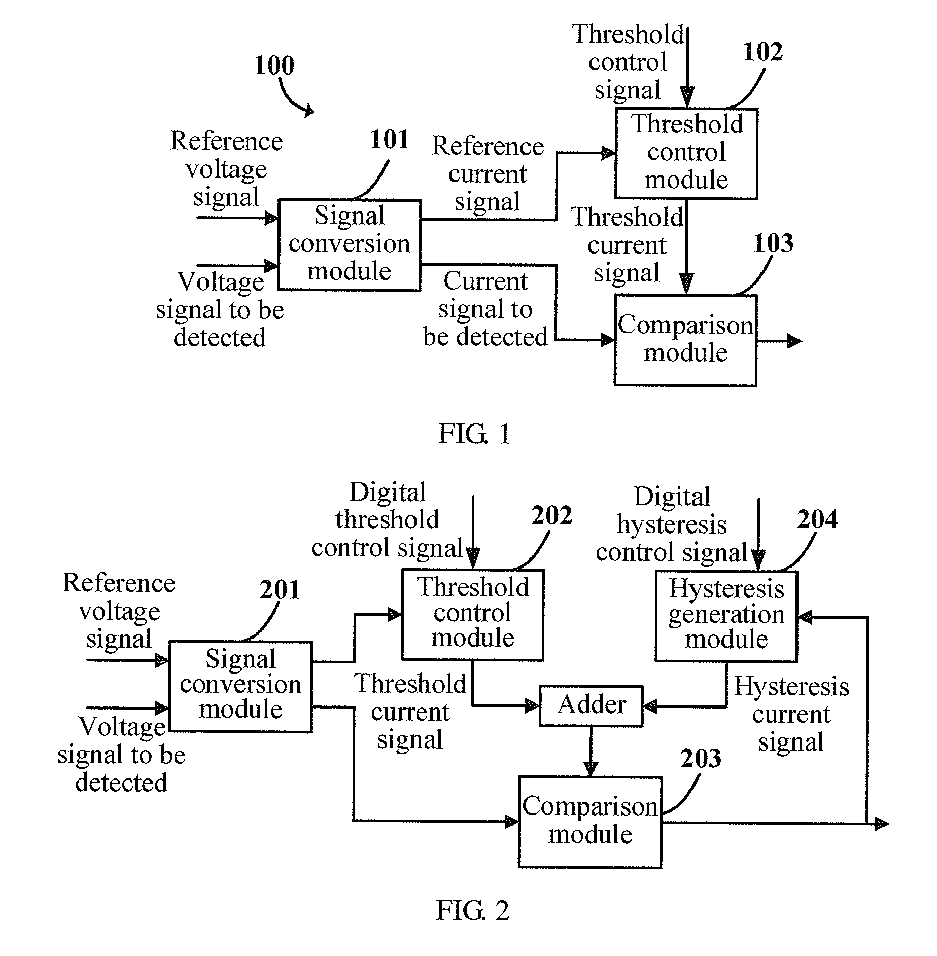
[0030]As shown in FIG. 1, a signal detection circuit 100 is provided in an embodiment of the present invention. The circuit includes a signal conversion module 101, a threshold control module 102, and a comparison module 103.

[0031]The signal conversion module 101 is configured to: convert a reference voltage signal into a reference current signal, and send the reference current signal to the threshold control module; and convert a voltage signal to be detected into a current signal to be detected, and send the current signal to be detected to the comparison module.

[0032]The threshold control module 102 is configured to: generate a threshold current signal according the reference current signal, and send the threshold current signal to the comparison module; and receive a threshold control signal that is input acco...


PUM


Abstract

A signal detection circuit is provided, and includes a signal conversion module, a threshold control module, and a comparison module. The signal conversion module is configured to: convert a reference voltage signal into a reference current signal, and send the reference current signal to the threshold control module; convert a voltage signal to be detected into a current signal to be detected, and send the current signal to be detected to the comparison module. The threshold control module is configured to: generate a threshold current signal according the reference current signal, and send the threshold current signal to the comparison module; and receive a threshold control signal, and change magnitude of the threshold current signal according to the threshold control signal. The comparison module is configured to compare magnitude of the current signal to be detected with the magnitude of the threshold current signal, and output a comparison result.

Description

CROSS-REFERENCE TO RELATED APPLICATIONS[0001]This application claims priority to Chinese Patent Application No. 201010506141.2, filed on Sep. 30, 2010, which is hereby incorporated by reference in its entirety.FIELD OF THE INVENTION[0002]The present invention relates to the field of communications technologies, and in particular, to a circuit, a method, and a system for signal detection.BACKGROUND OF THE INVENTION[0003]Currently, Local Area Networks (hereinafter referred to as LANs) are generally based on the 10BASE-T, 100BASE-T, and 1000BASE-T protocols, and receive and send signals by using twisted-pair cables. When a Physical Layer Device (hereinafter referred to as PHY) of a sender communicates with a PHY of a receiver, the sender and the receiver both need to send a 10 Mbps link signal or a 100 Mbps signal (hereinafter referred to as a negotiation signal) to the other party. The negotiation signal is used to notify the other party of communication capability of the sender or th...

Claims


Application Information

Patent Timeline
IPC IPC(8): G01R19/00
CPCG01R19/16566G01R19/16519
Inventor WANG, ZHENGXIANG
Owner HUAWEI TECH CO LTD
Why Eureka
Try Eureka