Light sensor readout system and method of converting light into electrical signals

a light sensor and readout system technology, applied in the direction of amplifiers with semiconductor devices/discharge tubes, amplifier combinations, amplifier modifications to reduce noise influence, etc., can solve the problems of reducing the accuracy of current-to-voltage conversion, increasing the risk of common mode signals or noise, and enhancing the overall sensitivity. , to achieve the effect of enhancing signal detection

Active Publication Date: 2017-04-27
GOOGLE LLC
View PDF1 Cites 3 Cited by
  • Summary
  • Abstract
  • Description
  • Claims
  • Application Information

AI Technical Summary

Benefits of technology

[0003]Embodiments of the disclosed subject matter provide systems and methods of converting light received by a sensor into electrical signals to be output. The received light may include one or more of visible light, infrared light, and / or ultraviolet light. The systems may include resistors configured in a T-network that are coupled to a transimpedance amplifier to amplify the current from a sensor which converts received light into the current. Embodiments of the disclosed subject matter may include an instrumentation amplifier to replace transimpedance amplifiers in sensor (e.g., photodiode) readout circuitry. The embodiments enhance signal detection by rejection of common mode signals and noise, and by converting the desired signal into a differential signal to further enhance overall sensitivity.

Problems solved by technology

When producing transimpedance amplifiers using high-volume manufacturing techniques, the higher the value of the desired resistance for the resistor of the transimpedance amplifier, the more susceptible the resistor is to temperature, humidity, and contamination, which will degrade the accuracy of the current-to-voltage conversion.
Also, typical transimpedance amplifiers generally do not provide adequate rejection of a common mode signal, thereby leaving the current-to-voltage conversion more susceptible to the common mode signal or noise (which could appear as a common mode signal).

Method used


Image

  • Light sensor readout system and method of converting light into electrical signals
  • Light sensor readout system and method of converting light into electrical signals
  • Light sensor readout system and method of converting light into electrical signals

Examples


Embodiment Construction

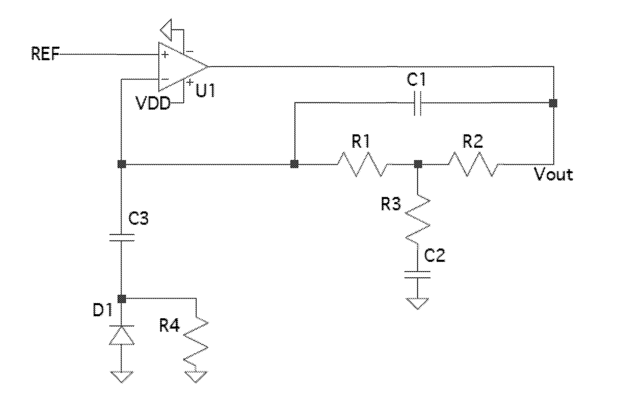
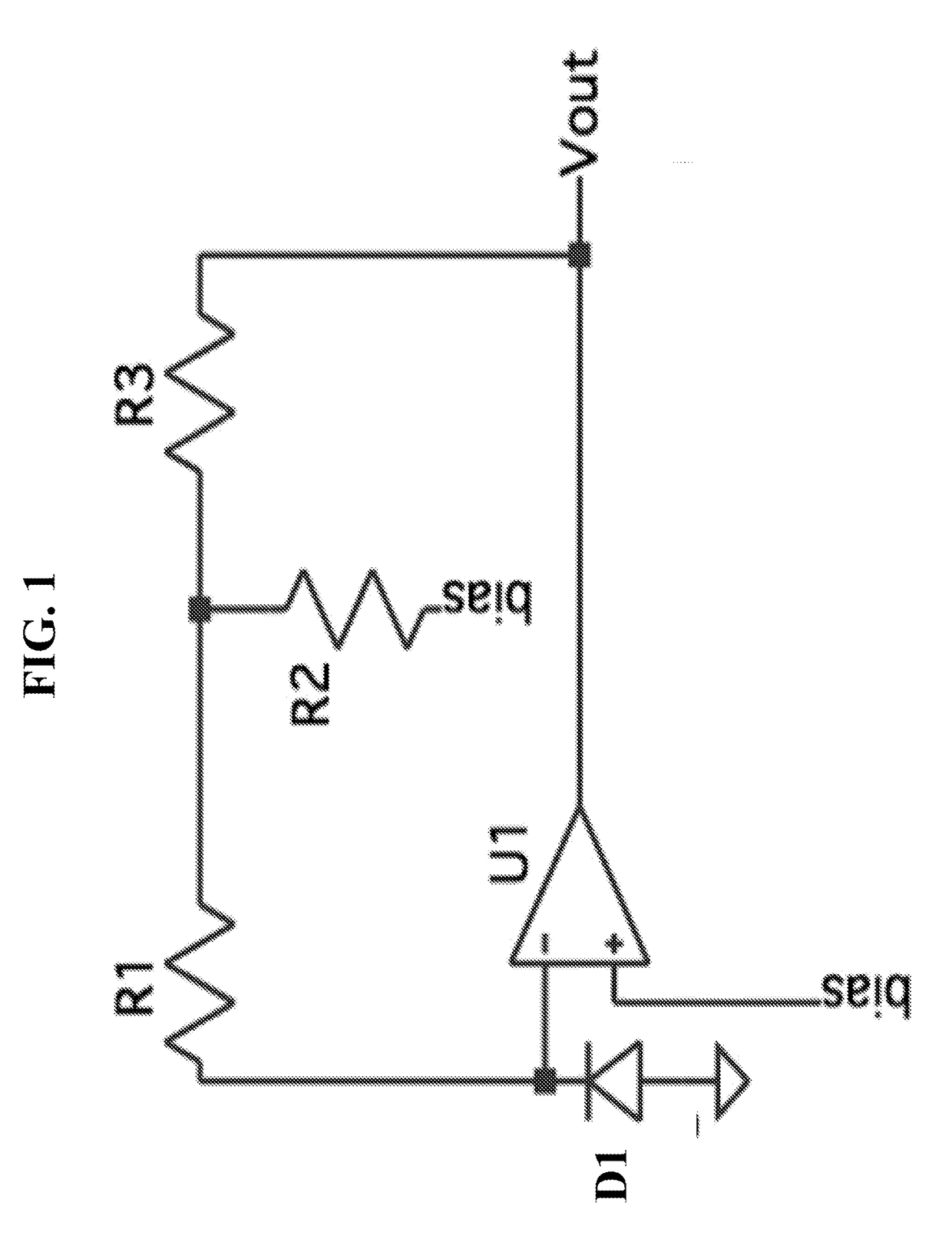
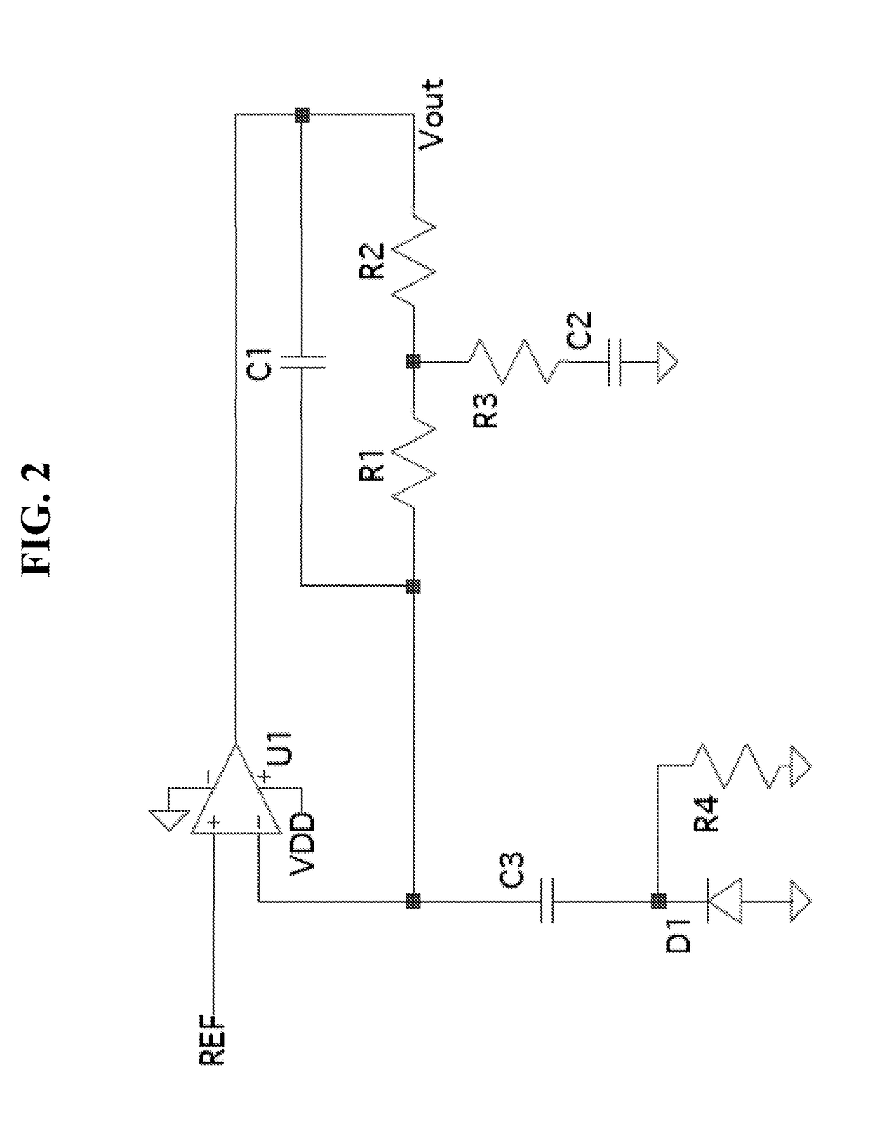
[0024]Embodiments of the disclosed subject matter provide systems and methods of converting light received by a sensor into electrical signals to be output. The received light may be visible light, IR light, and / or ultraviolet light. The systems may include resistors configured in a T-network that are coupled to a transimpedance amplifier to amplify the current from a sensor which converts received light into the current. The T-network configuration of resistors avoids the typical use of a single, high-valued resistor, which is often susceptible to temperature, humidity, and contamination, which degrades the accuracy of a conversion (e.g., current to voltage conversion). The embodiments of the disclosed subject matter avoid the use of an additional amplifier that is typically found in other related systems to raise the output signal above a predetermined noise floor. The systems of the disclosed subject matter may have increased suitability for high-volume manufacturing, as they are...


PUM


Abstract

Systems and methods of the disclosed subject matter for converting light into electrical signals are provided including receiving light input and outputting electrical signals proportional to the light input with a sensor, increasing a transimpedance gain of an amplifier to amplify the electrical signals with a T-network of resistors coupled to the amplifier and the sensor, filtering the electrical signals with a filter circuit coupled to the amplifier and the T-network of resistors to increase noise rejection in a predetermined frequency range, and outputting the filtered electrical signals.

Description

BACKGROUND[0001]Infrared (IR) light signals can be output using light emitting diodes (LEDs), and can be received by a sensor to convert the light into an electrical signal. That is, IR light can be modulated to form an IR light signal including control signals or other information, and the IR light signal can be detected by a sensor. The sensor and related circuity can convert the light into electrical signals, and output a control signal or a data signal from the recovered electrical signals.[0002]A received IR light signal is typically measured with a photodiode sensor, and can have a current that ranges from 1 pA to 1 nA. To amplify the current, a transimpedance amplifier is typically used with a high-valued resistor, which is generally greater than 10 MΩ. When producing transimpedance amplifiers using high-volume manufacturing techniques, the higher the value of the desired resistance for the resistor of the transimpedance amplifier, the more susceptible the resistor is to temp...

Claims


Application Information

Patent Timeline
Patent Type & Authority Applications(United States)
IPC IPC(8): H03F3/45H03F1/26H03F1/56H03F3/68
CPCH03F3/45H03F3/68H03F2200/171H03F1/56H03F2203/45078H03F1/26H03F3/087H03F3/211H03F3/45475H03F3/45928H03F2203/45138H03F3/08
Inventor AINA, MORAKINYO JOHNHEYL, LAWRENCE
Owner GOOGLE LLC
Why Eureka
Try Eureka