
Combinations of axial and saddle coils to create the equivalent of tilted coils for directional resistivity measurements

Active Publication Date: 2012-04-05
SCHLUMBERGER TECH CORP
View PDF4 Cites 18 Cited by
  • Summary
  • Abstract
  • Description
  • Claims
  • Application Information

AI Technical Summary

Problems solved by technology

One disadvantage of a connecting two separate coils, in series particularly, is that relative phase and gain changes between the coils can be significant.
Such changes are typically not compensated for when making both upward and downward measurements.

Method used


Image

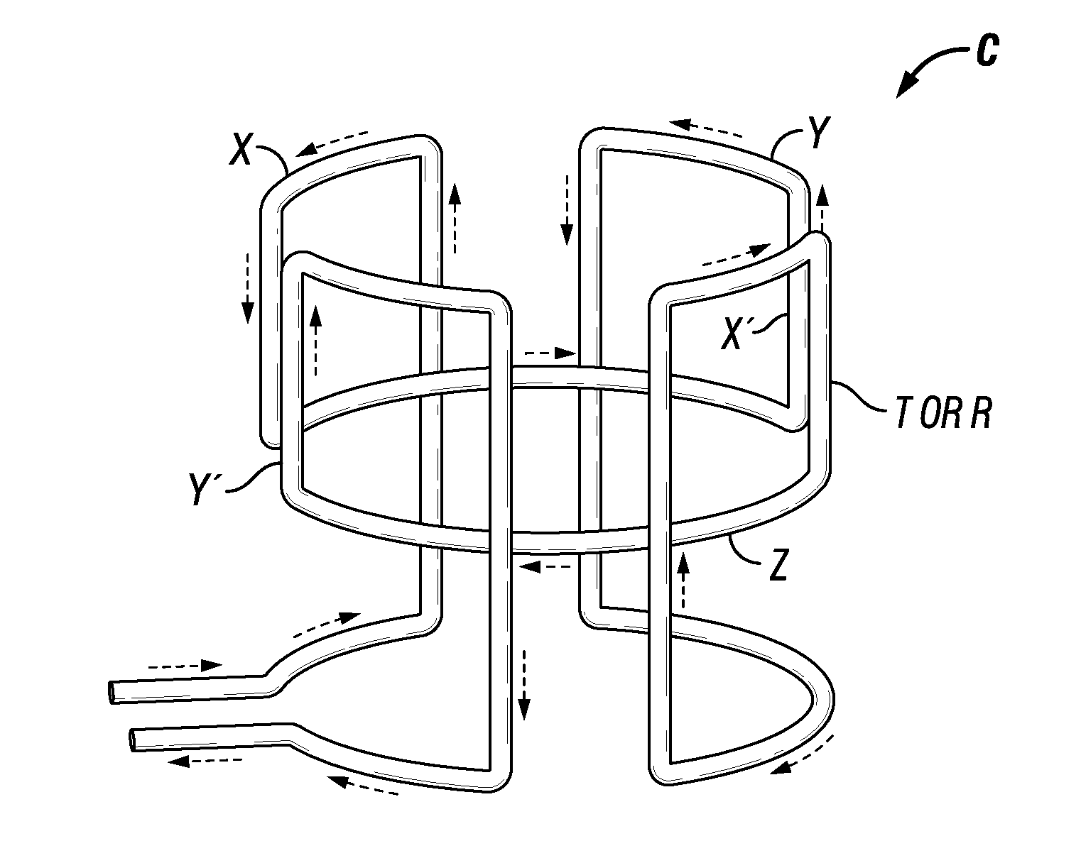
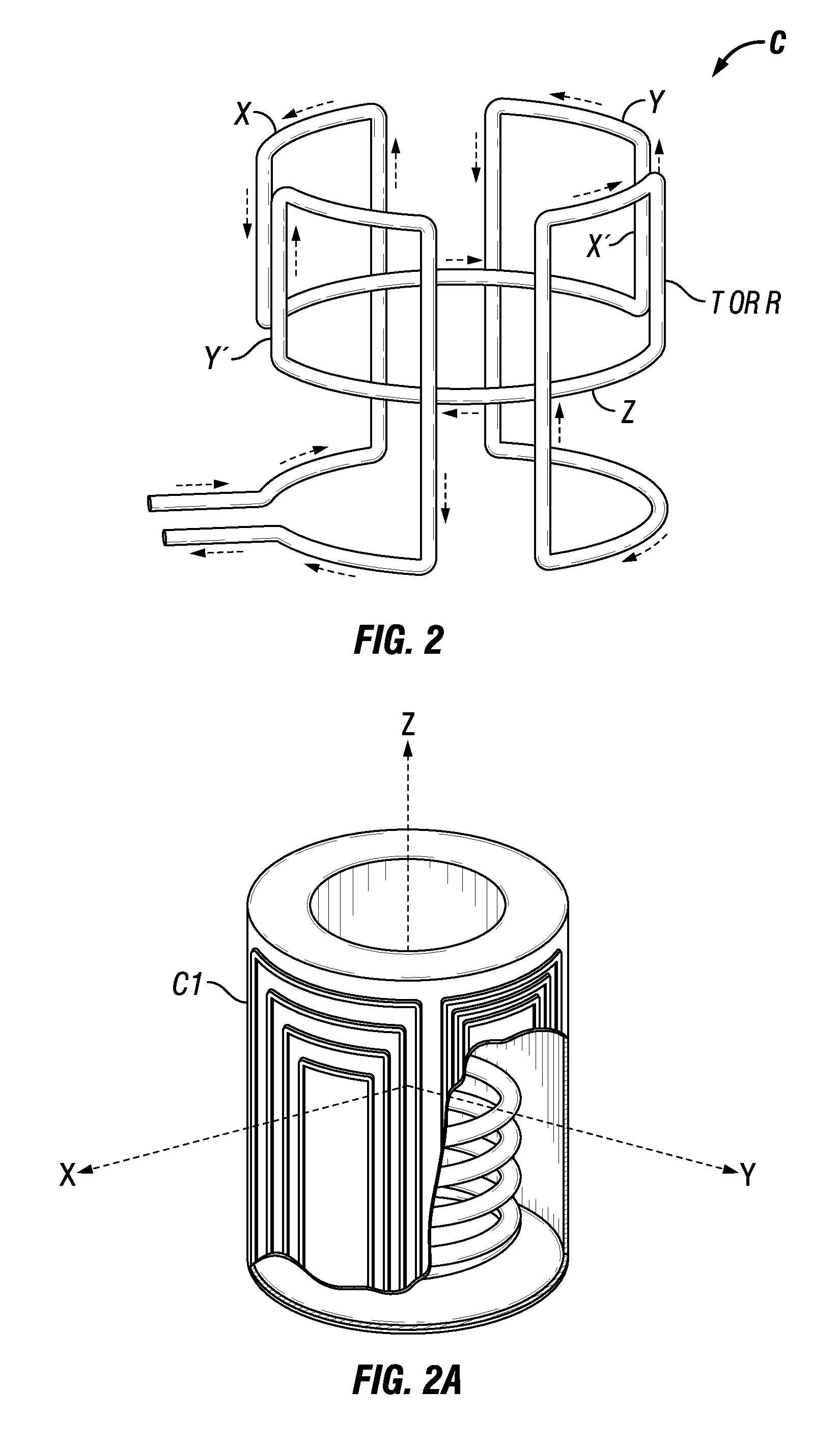
  • Combinations of axial and saddle coils to create the equivalent of tilted coils for directional resistivity measurements
  • Combinations of axial and saddle coils to create the equivalent of tilted coils for directional resistivity measurements
  • Combinations of axial and saddle coils to create the equivalent of tilted coils for directional resistivity measurements

Examples


Embodiment Construction

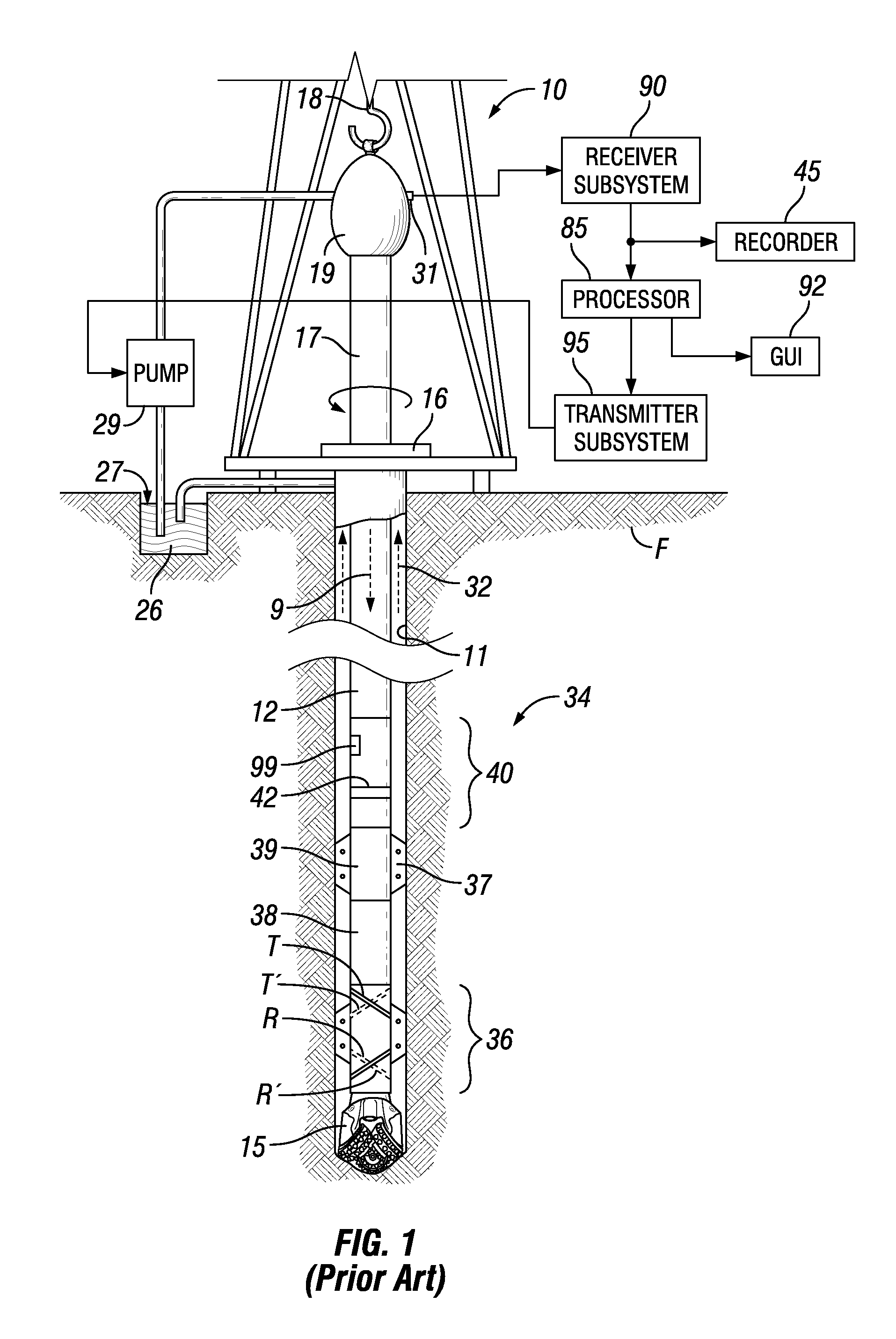
[0020]FIG. 1 illustrates a conventional drilling rig and a drill string in which an instrument for performing a method according to the present invention can be used. A land-based platform and derrick assembly 10 are shown positioned over a wellbore 11 penetrating a subsurface rock formation F. In the illustrated example, the wellbore 11 is formed by rotary drilling in a manner that is well known. Those of ordinary skill in the art given the benefit of this disclosure will appreciate, however, that the present invention also finds application in directional drilling, for example, using rotary steerable directional drilling systems or “steerable” hydraulic motors. Further, the invention is not limited to land-based drilling but is equally applicable in marine wellbore drilling.

[0021]A drill string 12 is suspended within the wellbore 11 and includes a drill bit 15 at its lower end. The drill string 12 can be rotated by a rotary table 16, energized by means (not shown) which engages a ...


PUM


Abstract

An electromagnetic well logging instrument includes an instrument housing, at least one transmitter coil disposed on the housing and at least one receiver coil disposed on the housing. At least one of the transmitter and receiver coils is formed from a combination solenoidal (axial) and saddle coils. The net dipole moment direction of the combined coil is determined by selecting the relative turn-areas of the saddle and solenoidal coil. The combined coil can be formed from a single wire wound to have both a longitudinal magnetic dipole moment and a transverse magnetic dipole moment with respect to a longitudinal axis of the housing.

Description

CROSS-REFERENCE TO RELATED APPLICATIONS[0001]Priority is claimed from U.S. Provisional Application No. 61 / 353,587 filed on Jun. 10, 2010STATEMENT REGARDING FEDERALLY SPONSORED RESEARCH OR DEVELOPMENT[0002]Not applicable.BACKGROUND[0003]The invention relates generally to the field of electromagnetic surveying of subsurface formations from within a wellbore. More specifically, the invention relates to structures for antennas for wellbore electromagnetic surveying that have azimuthally variant sensitivity.[0004]U.S. Pat. No. 6,969,994 issued to Minerbo et al. and assigned to the assignee of the present invention describes one example of a well logging instrument including both longitudinal magnetic dipole and tilted magnetic dipole antennas so that, among other functions, distances between a wellbore and a formation boundary can be estimated in the presence of anisotropy and relative dip (angle between the wellbore axis and the direction of layering of the subsurface formations.[0005]T...

Claims


Application Information

Patent Timeline
IPC IPC(8): G01V3/30
CPCG01V3/28
Inventor FREY, MARK T.
Owner SCHLUMBERGER TECH CORP
Learn More