Low-ductility open channel turbine shroud

a technology of open channel turbines and low-ductility, which is applied in the direction of machines/engines, mechanical equipment, liquid fuel engines, etc., can solve the problem of potentially dependent design of clamps

Active Publication Date: 2012-04-05
GENERAL ELECTRIC CO
View PDF11 Cites 89 Cited by
  • Summary
  • Abstract
  • Description
  • Claims
  • Application Information

AI Technical Summary

Benefits of technology

[0008]According to another aspect of the invention, a turbine shroud apparatus for a gas turbine engine includes: a plurality of arcuate shroud segments arranged to form an annular shroud, each of the shroud segments comprising low-ductility material and having a cross-sectional shape defined by opposed forward and aft walls, and opposed inner and outer walls, the walls extending between opposed first and second end faces, wherein an open channel is formed through the outer wall of each shroud segment; an annular stationary structure surrounding the shroud segments; and a hanger received in the open channel of each shroud segment and mechanically coupled to the stationary structure, each of the hangers passing through the respective open channel and having a T-shaped cross section comprising a central portion extending through the open channel, flanked by at least one laterally-extending rail which engages the outer wall of the respective shroud segment, so as to retain the shroud segment in a radial direction relative to the stationary structure.

Problems solved by technology

This can lead to problems if the frictional loading from clamping is larger than the axial load on the shroud, because the shroud needs to stay in contact with an axial stop to maintain proper sealing.
This makes the clamped design potentially dependent on frictional forces which can be inconsistent.

Method used


Image

  • Low-ductility open channel turbine shroud
  • Low-ductility open channel turbine shroud
  • Low-ductility open channel turbine shroud

Examples


Embodiment Construction

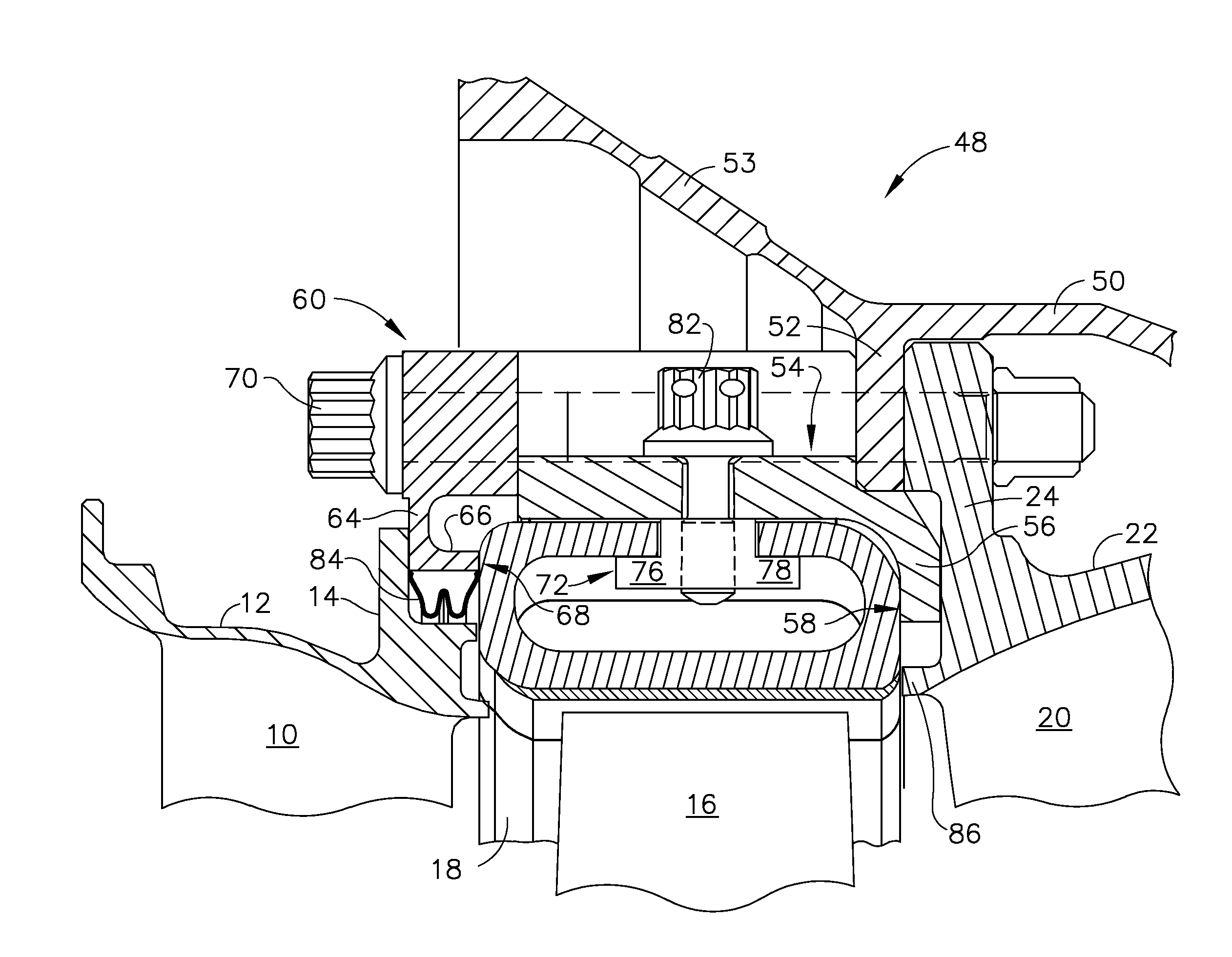
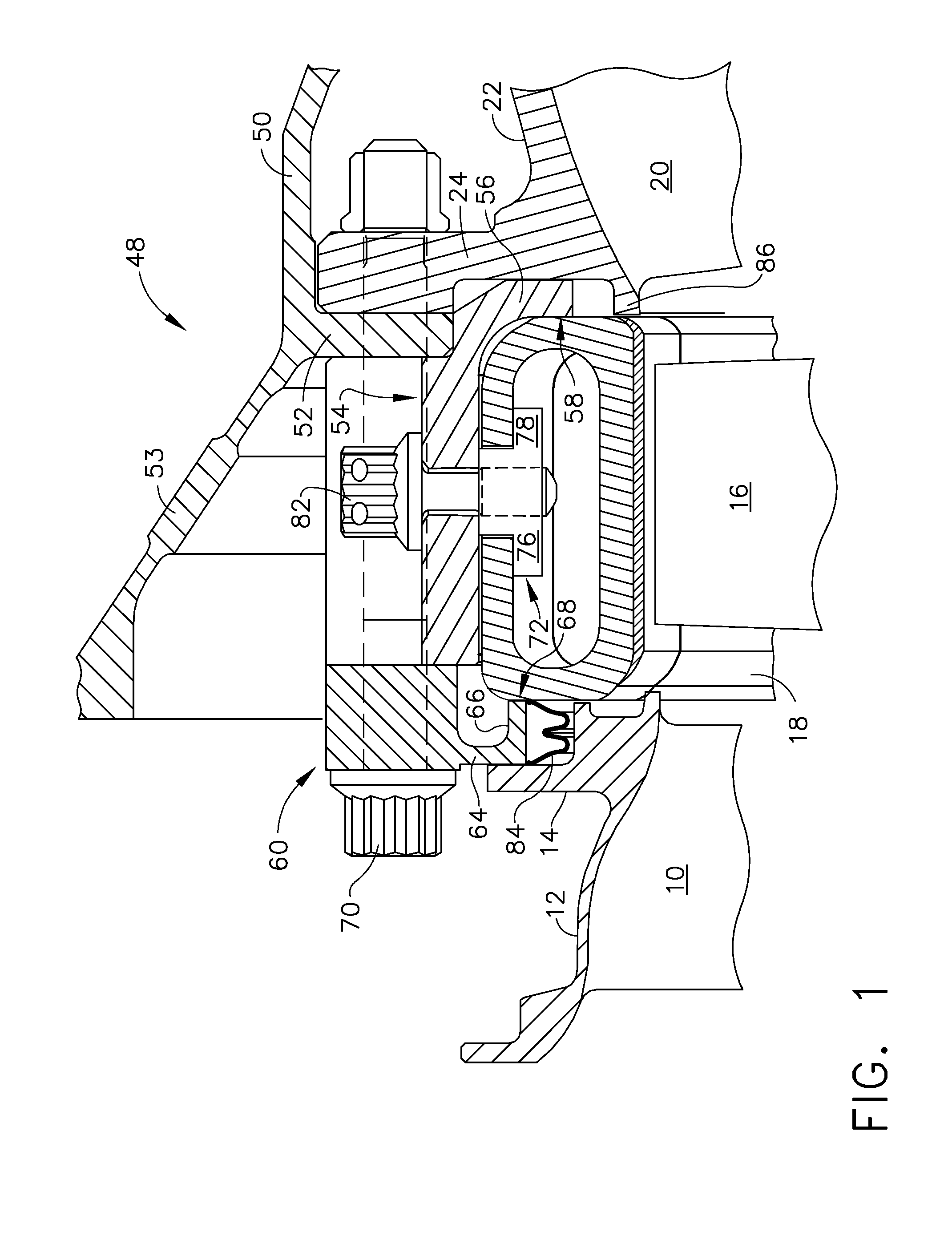
[0017]Referring to the drawings wherein identical reference numerals denote the same elements throughout the various views, FIG. 1 depicts a small portion of a gas generator turbine (also referred to as a high pressure turbine), which is part of a gas turbine engine of a known type. The function of the gas generator turbine is to extract energy from high-temperature, pressurized combustion gases from an upstream combustor (not shown) and to convert the energy to mechanical work, in a known manner. The gas generator turbine drives an upstream compressor (not shown) through a shaft so as to supply pressurized air to the combustor.

[0018]In the illustrated example, the engine is a turboshaft engine and a work turbine would be located downstream of the gas generator turbine and coupled to a shaft driving a gearbox, propeller, or other external load. However, the principles described herein are equally applicable to turbojet and turbofan engines, as well as turbine engines used for other ...


PUM


Abstract

A turbine shroud apparatus for a gas turbine engine includes: a plurality of arcuate shroud segments arranged as an annular shroud, each of the shroud segments comprising low-ductility material and having a cross-sectional shape defined by opposed forward and aft walls, and opposed inner and outer walls, the walls extending between opposed first and second end faces, wherein an open channel is formed through the outer wall of each shroud segment; an annular stationary structure surrounding the shroud segments; and a hanger received in the open channel of each shroud segment and mechanically coupled to the stationary structure, each of the hangers passing through the respective open channel and including an enlarged portion having greater cross-sectional area than the open channel, the enlarged portion engaging the outer wall of the respective shroud segment, so as to retain the shroud segment radially relative to the stationary structure.

Description

BACKGROUND OF THE INVENTION[0001]This invention relates generally to gas turbine engines, and more particularly to apparatus for mounting shrouds made of a low-ductility material in the turbine sections of such engines.[0002]A typical gas turbine engine includes one or more turbine rotors which extract energy from the primary gas flow. Each rotor comprises an annular array of blades or buckets carried by a rotating disk. The flowpath through the rotor is defined in part by a shroud, which is a stationary structure which circumscribes the tips of the blades or buckets. These components operate in an extremely high temperature environment, and must be cooled by air flow to ensure adequate service life. Typically, the air used for cooling is extracted (bled) from the compressor. Bleed air usage negatively impacts specific fuel consumption (“SFC”) and should generally be minimized.[0003]It has been proposed to replace metallic shroud structures with materials having better high-temperat...

Claims


Application Information

Patent Timeline
Patent Type & Authority Applications(United States)
IPC IPC(8): F01D11/08
CPCF01D11/005F01D11/125F05D2260/20F05D2240/11F05D2240/55F01D25/246
Inventor DZIECH, AARONALBERS, JOSEPHJOHNSON, CHRISTOPHER RYAN
Owner GENERAL ELECTRIC CO
Why Eureka
Try Eureka